


Appendix
44
ProtoMat M60
All signals are electrically galvanically decoupled; all contacts not
mentioned are not used.
8.4 Serial port SERIAL 2
The serial data channel SERIAL 2 is an RS 232-C standard interface
and can be used for communication between the control unit and
another system. The transmission speed of SERIAL 2 is programmed
with DIL switches 3 and 4.
SERIAL 2 settings:
All contacts not mentioned are not used.
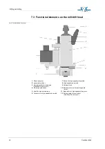
8.5 Motor connection
The stepping motors are connected per axis via a 15-pole SUB-D plug. If
the limit switch is actuated, any further axis movement in the direction of
the limit switch is immediately blocked. The position of the sockets is
described in the section see „Displays and connections“ on page 15.
Another 5-pole cable is used to supply the high-speedcycle spindle with
power.
Caution! Never confuse the stepper motor and the mill/drill head
cables!
7
GND-I
Ground (isolated)
8
DCD
Data carrier detect
20
DTR
Data terminal ready
Switch 3
Switch 4
Baud-rate
OFF
OFF
4600 baud
ON
OFF
9600 baud
OFF
ON
19200 baud
ON
ON
-
PIN
Signal
Meaning
3
TXD
Transmit data
2
RXD
Receive data
7
RTS
Request to send
8
CTS
Clear to send
5
GND
Ground


