


Milling and drilling
38
ProtoMat M60
7.13 Practical tips
• Set the milling depth such that
engraving is too deep
rather
than too shallow. Insufficient depth when engraving promotes
milling tool wear.
• There can be a number of causes of
uneven milling width
(depth)
.
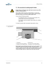
• It is important that the
machine bed is clean
.
•
Residues of adhesive tape
or such like can adversely
affect milling depth quite considerably.
• Also,
milling swarf
between the machine bed, drilling
support and PCB can reduce precision.
• Greatly
distorted materials
bend such that the sag shows
underneath; in this case, secure the edges well with adhesive
tape.
• Another important point for precise milling depth is the
removal
of milling and drilling chips.
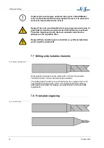
•
Hooks
can occur
between the milling channels
if the incorrect
milling direction sequence was specified followed, in particular
with circles. If a circle is to be milled with a tool which rotates
clockwise,
fine hooks
can arise between the copper areas if the
milling tracks should overlap. The reason for this is that the
cutting speed on the outer edges is reduced.
The solution lies in selecting the right milling direction. When
isolating conductor paths with LPKF isolate, the solder side
should be mirrored before isolating as the isolation algorithm
itself works in a clockwise direction. The standard postprocessing
is already designed for this.
CircuitCAM
allows the user to select
the direction of the milling tool and therefor mirroring prior to
isolation is not necessary.
•
Milling burrs
can be caused by blunt tools or incorrect speeds of
movement. If possible with the structure to be milled, deeper
settings can be the answer. Otherwise, change the tool.
•
Burrs when contour milling
or
cut edges which are not clean
occur either due to a blunt tool or incorrect advance speed.
• With some materials, the
color of the milled channel
gives
some indication of the state of the tool. With epoxy materials,
dark isolation paths indicate a sharp tool, while lighter ones
indicate a blunter tool.
•
Drilling burrs
occur either because the tool is blunt or the head
lowering speed is excessive. In the first case, change the tool. In
the second case, the tool height over the material must be
reduced.
•
Drill deflection
occurs in particular with thin tools which are no
longer absolutely sharp. However, this also depends on the
surface structure of the material. If, for example the glass fiber
structure of FR4 materials penetrates the copper, drill deflection
cannot be avoided even with a sharp tool. For materials with
additional, removable copper film (FR4 material with 18 µm or 9
µm Cu coating), drill deflection is very slight. With an additional
processing step all drillings can first be marked. This also avoids
the deviation of the drill.


