background image

30

R

Section 7

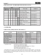
MAINTENANCE CHART - RECOMMENDED SERvICE INTERvALS

7.1 

HOURS

PROCEDURE

COMMENTS

BREAk-IN 

(FIRST 10)

8

40

100

200

500

X

Check all hardware for tightness

X

Check hydraulic oil level

See paragraph 7.3

X

C h e c k   a l l   b e l t s   f o r   p r o p e r 
alignment

See paragraph 7.8

X

Change engine oil and filter

See paragraph 7.4

X

Check coolant level

See paragraph 7.11

X

Check hydraulic hoses for leaks

Use extreme caution when 
checking the hydraulic hoses. 
See paragraph 2.6

X

Check engine oil level

See paragraph 7.4

X

*Clean mower

See paragraph 7.12

X

Check condition of blades

See paragraph 7.9

X

Apply grease to fittings

See paragraph 7.2

X

Check tire pressure

See paragraph 7.10

X

I n s p e c t   s e a t   b e l t   fo r   we a r   o r 
damage

See paragraph 2.5

X

C h e ck   t h e   o p e ra t o r   i n t e r l o ck 
system

See paragraph 4.2

X

Check coolant level

See paragraph 7.11

X

Check  batter y  electrolyte  level 
clean battery posts and cables

See paragraph 7.7

X

Check belts for proper alignment

See paragraph 7.8

X

Apply grease to fittings

See paragraph 7.2

X

Change engine oil

See paragraph 7.4

X

*Clean air cleaner element 

See paragraph 7.6

X

Check  lubricant  in  cutter  deck 
gearbox

See paragraph 7.11

* Perform these maintenance procedures more frequently under extreme dusty or dirty conditions

MAINTENANCE

Содержание LVR-880 EU

Страница 1: ...structions and safety information for your Scag mower Reading this manual can provide you with assistance in maintenance and adjustment procedures to keep your mower performing to maximum efficiency The specific models that this book covers are listed on the inside cover Before operating your machine please read all the information enclosed OPERATOR S MANUAL Turf Tiger Model STT61V 31EFI SS ...

Страница 2: ...Before performing any maintenance or service stop the machine and remove the spark plug wire and ignition key If a mechanism becomes clogged stop the engine before cleaning Keep hands feet and clothing away from power driven parts Keep others off the mow er only one person at a time REMEMBER YOUR MOWER IS ONLY AS SAFE AS THE OPERATOR Hazard control and accident prevention are dependent upon the aw...

Страница 3: ...ter Deck 11 3 5 Hydraulic System 11 3 6 Weights And Dimensions 11 3 7 Productivity 11 OPERATING INSTRUCTIONS SECTION 4 12 4 1 Controls And Instrument Identification 12 4 2 Safety Interlock System 13 4 3 Initial Run In Procedures 14 4 4 Starting The Engine 14 4 5 Ground Travel And Steering 14 4 6 Engaging The Deck Drive Cutter Blades 15 4 7 Hillside Operation 16 4 8 Parking The Mower 16 4 9 After O...

Страница 4: ...Cutter Blades 37 7 10 Tires 38 7 11 Cutter Deck Gearbox 38 7 12 Cooling System 39 7 13 Body Deck And Upholstery 40 ILLUSTRATED PARTS LIST SECTION 8 41 8 1 Scag Approved Attachments And Accessories 41 61V CUTTER DECK 42 CUTTER DECK CONTROLS 44 SHEET METAL COMPONENTS 46 STT ROLL OVER PROTECTION SYSTEM WITH SUSPENSION SEAT 48 DECK DRIVE COMPONENTS 50 ENGINE ATTACHING PARTS 31HP EFI KOHLER 52 BRAKE AN...

Страница 5: ... 9 0 3 4 9 2 0 7 3 3 4 9 6 7 5 4 3 4 9 9 1 3 8 2 4 9 9 8 9 4 8 5 1 1 8 6 1 7 5 8 2 6 4 1 6 5 8 3 2 7 0 8 5 8 6 5 0 1 8 Mower Serial Number Plate Location Figure 1 1 GENERAL INFORMATION USE ONLY SCAG APPROVED ATTACHMENTS AND ACCESSORIES Attachments and accessories manufactured by companies other than Scag Power Equipment are not approved for use on this machine See Section 8 1 WARNING For pictorial...

Страница 6: ...sly Variable Linear Cutting Element Basic Symbol 481039S Pinch Point Cutting Element Engage Hour meter Elapsed Operating Hours Cutting Element Disengage STT Models Seat must be installed under the seat hold down bracket during installation Failure to secure the seat under the hold down bracket could result in serious injury or death in a roll over CE Mark Thrown Object Hazard Keep Bystanders Away ...

Страница 7: ...ry and possible death carefully read the message Be sure to fully understand the causes of possible injury or death Signal Word It is a distinctive word found on the safety decals on the machine and throughout this manual that alerts the viewer to the existence and relative degree of the hazard Danger The signal word DANGER denotes that an extremely hazardous situation exists on or near the machin...

Страница 8: ...l 11 tank outdoors Never fill it indoors Use a funnel or spout to prevent spillage Clean up any spillage before starting the engine DO NOT add fuel to a running or hot engine Allow 12 the engine to cool for several minutes before adding fuel Never fuel indoors or inside enclosed trailers Keep flammable objects cigarettes matches etc 13 open flames and sparks away from the fuel tank and fuel contai...

Страница 9: ...aged 12 Take all possible precautions when leaving the 13 machine unattended such as disengaging the mower lowering the attachments setting the parking brake stopping the engine and removing the key Disengage power to the attachments when 14 transporting or when not in use The machine and attachments should be stopped 15 and inspected for damage after striking a foreign object and damage should be...

Страница 10: ...1 Roll Over Protection System 2 5 WARNING Reduce speed when turning operating on slopes slick or wet surfaces Allow extra distance to stop Stay off of slopes too steep for safe operation To check a slope attempt to back up it with the cutter deck down If the machine can not back up the slope without the wheels slipping do not operate the machine on this slope Under no circumstances should the mach...

Страница 11: ... significant discoloration due to UV exposure dirt or stiffness abrasion to the seat belt webbing or damage to the buckle latch plate hardware or any other obvious problem should be replaced immediately WARNING Failure to properly inspect and maintain the seat belt can cause serious injury or loss of life Check the full length of the seat belt webbing for 1 cuts wear fraying dirt and stiffness See...

Страница 12: ...s leaves excessive grease oil and dirt Park the machine on level ground and engage the 7 parking brake NEVER allow untrained personnel to service the 8 machine Use care when checking blades Use a Blade Buddy 9 wrap the blade s or wear gloves and USE CAUTION when servicing blades Only replace blades NEVER straighten or weld blades Keep all parts in good working condition Replace all 10 worn or dama...

Страница 13: ...ructional Decals 2 7 WARNING INSTALL BELT COvER BEFORE OPERATING MACHINE READ OPERATOR S MANUAL 483402 390S0150G 481568 FORWARD REvERSE F R 482710 483397 483406 483407 483402 483444 483407 483397 483633 483425 483429 483300 483444 ...

Страница 14: ...l Control Mower Engagement BBC Parking Brake Instrument Panel Volt Meter Key Switch Throttle Lever BBC Switch Fuses and Safety Start module Water Temperature Gauge Fuses Two 2 20 Amp Power Head 3 3 Drive System Hydraulic Drive with Two Variable Displacement Pumps and Two Cast iron High Torque Motors Hydrostatic Pumps Two Hydro Gear 16 cc rev Pumps with Dump Valves Belts Kevlar cord Self adjusting ...

Страница 15: ...vy duty 1 1 8 Top Dimension Spindle Shaft Cast Housing Taper Roller Bearing Low Maintenance with Top Access Grease Fitting and Grease Overfill Relief Poppet Spindle Pulleys Split Steel with Easily Removed Taper Hubs Cutter Deck Belts B Section with Kevlar Cord Self adjusting Self tightening Electric Clutch Type Ogura Heavy Duty PTO Clutch Brake Drive Shaft Clamp Yoke Shaft With Two High Speed U Jo...

Страница 16: ...ill disengage the deck drive Engine Throttle Control Figure 4 1 3 Used to control the engine speed Pushing the lever forward increases engine speed Pulling the lever back decreases engine speed Full back position is the IDLE position Full forward is the cutting position Volt Meter Figure 4 1 4 Indicates the condition of the charging system When the engine is running the needle should be toward the...

Страница 17: ...tter deck Push full forward to lock in the transport position Cutting Height Adjustment Figure 4 1 13 Used to set the cutter deck at the desired cutting height Deck Release Lever Figure 4 1 14 Used to lock the cutter deck in the transport position Push the foot pedal forward and pull back on the release lever to release the cutter deck for normal mowing Temperature Gauge Figure 4 1 15 Indicates th...

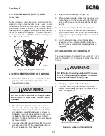
Страница 18: ...ter motor and shorten battery life Allow engine to warm before operating the mower 9 Ground Travel And Steering 4 5 IMPORTANT If you are not familiar with the operation of a machine with lever steering and or hydrostatic transmissions the steering and ground speed operations should be learned and practiced in an open area away from buildings fences or obstructions Learn the operation on flat groun...

Страница 19: ...ile traveling in reverse allow the right steering control lever to move forward The further the control is allowed to move forward the quicker the mower will turn right To stop the reverse travel allow the steering control levers to return to the neutral position If the mower is to be parked place the handles in the neutral lock position and engage the parking brake Engaging The Deck Drive Cutter ...

Страница 20: ... surface only Do not 1 park the machine on an incline Place the steering control levers in the neutral 2 position Disengage the cutter blades 3 Slow the engine to idle speed 4 Engage the parking brake 5 Turn the ignition key to the OFF position and remove 6 the key After Operation 4 9 Wash the entire mower after each use Do not 1 use high pressure spray or direct the spray onto electrical componen...

Страница 21: ... Cut grass when it is dry and not too tall Do not cut 3 grass too short cut off 1 3 or less of existing grass for best appearance Mow frequently Keep mower and discharge chute clean 4 When mowing wet or tall grass mow the grass twice 5 Raise the mower to the highest setting for the first pass and then make a second pass to the desired height Use a slow travel speed for trimming purposes 6 Operate ...

Страница 22: ...y B Rotate the steering lever forward or backward to achieve the optimum operating position C Tighten the tension knob and repeat on the opposite side D While in the operator s position bring the steering levers out of the neutral lock position and check to make sure both levers are even before operating TENSION kNOB TENSION kNOB ROTATE LEvER Adjusting Steering Levers Figure 4 7 The control handle...

Страница 23: ...ch towed equipment except at the hitch point Follow manufacturer s recommendations for weight 3 limit for towed equipment 250 lbs maximum towing weight NEVER tow on slopes The weight of the towed 4 equipment may cause loss of traction and loss of control Travel slowly and allow extra distance to stop 5 Zero turning with a trailer attached could cause 6 damage to the trailer or mower ...

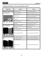
Страница 24: ...ing Strips of Uncut Grass in Cutting Path Width of Deck SGB018 Dull worn blades Sharpen blades Incorrect blade sharpening Sharpen blades Low engine RPM Run engine at full RPM Belt slipping Adjust belt tension Deck plugged grass accumulation Clean underside of deck Ground speed too fast Slow speed to adjust for conditions Wet grass Cut grass after it has dried out Bent blades Replace blades Streaki...

Страница 25: ...ler Bent spindle area See your authorized SCAG dealer Dull blade Sharpen blade Uneven Cut on Uneven Ground WavyAppearance High Low Scalloped Cut or Rough Contour Width of Deck SGB021 Uneven ground May need to reduce ground speed raise cutting height and or change direction of cut Sloping Ridge Across Width of Cutting Path Width of Deck SGB023 Tire pressures not equal Check and adjust tire pressure...

Страница 26: ...ut Ground speed too fast Slow speed to adjust for conditions Wet grass Cut grass after it has dried out Step Cut Ridge in Center of Cutting path Width of Deck SGB024 Blades not mounted evenly Adjust pitch and level Bent blade Replace blade Internal spindle failure See your authorized SCAG dealer Mounting of spindle incorrect See your authorized SCAG dealer Slope Cut Sloping Ridges Across Width of ...

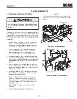
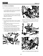
Страница 27: ...e specified measurement 3 adjust by loosening the jam nuts at both ends of the brake control rod and turning the rod until the proper distance is achieved See Figure 6 1 Tighten the jam nuts With the brake in the engaged position check the 4 spring compression between the two flat washers on the LH side of the machine The distance should be 1 7 16 See Figure 6 2 If the distance is not at the speci...

Страница 28: ...utral lock position With an operator in the seat start the engine and 2 disengage the parking brake Run the engine at full operating speed and check if 3 the machine creeps forward or backwards Adjust the RH wheel by loosening the jam nuts on 4 the steering control rod and turning the rod until the drive wheel turns in the forward direction Turn the rod back until the drive wheel stops moving Turn...

Страница 29: ...d to lengthen the rod and tighten the lock nuts This will cause the control rod to stroke the LH pump less slowing down the LH wheel See Figure 6 4 page 26 NOTE If after making the adjustment as outlined in step 1A the machine creeps forward or backward the neutral adjustment must be made as described on page 26 If at full speed the mower pulls left it is an indication 2 that the right wheel is tu...

Страница 30: ... Figure 6 5 Loosen the two 2 elastic stop nuts Adjust the bolt 2 up or down on the adjustment bracket to adjust the cutter deck until the distance from the bottom of the cutter deck to the floor is the same as the measurement on the RH side of the machine Tighten the two elastic stop nuts to secure the cutter 3 deck in the proper position Cutter Deck Pitch The pitch of the cutter deck should be eq...

Страница 31: ...C U T T IN G H E IG H T 6 5 5 5 4 5 4 3 5 3 2 5 2 1 5 1 48 15 43 HEIGHT ADJUSTMENT PEDAL LANYARD PIN LOOSEN HERE Cutter Deck Height Adjustment Figure 6 7 Turn the control rod See Figure 6 7 until there is a 2 1 4 space between the rear deck stop and the top of the cutter deck See Figure 6 8 Tighten the jam nuts on the control rod 1 4 DECK STOP 390S0175 1 Cutter Deck Stop Figure 6 8 Check the cutte...

Страница 32: ...fall cutting leaf pickup and reduce cutter deck blowout To adjust the Custom Cut Baffle height Place the cutter deck in the transport position 1 Remove the hardware securing the Custom Cut 2 Baffle to the cutter deck See Figure 6 9 NOTE Hardware location used in the illustrations are for reference only Location of hardware may vary depending on cutter deck size Move the Custom Cut Baffle to desire...

Страница 33: ... A 1 2 3 A 3 Position Custom Cut Baffle Adjustment Figure 6 9 1 2 34 A B 1 2 3 4 A B Custom Cut Baffle Adjustment Mounting Slot Selected Mounting Hardware Location Slot A Hole 1 Hole 2 Hole 3 Hole 4 Height inches 3 3 4 4 1 4 4 3 4 5 1 4 Slot B Hole 2 Hole 3 Hole 4 Height inches 3 1 2 4 4 1 2 7 Position Custom Cut Baffle Adjustment Figure 6 10 ...

Страница 34: ...agraph 7 12 X Check condition of blades See paragraph 7 9 X Apply grease to fittings See paragraph 7 2 X Check tire pressure See paragraph 7 10 X Inspect seat belt for wear or damage See paragraph 2 5 X Check the operator interlock system See paragraph 4 2 X Check coolant level See paragraph 7 11 X Check battery electrolyte level clean battery posts and cables See paragraph 7 7 X Check belts for p...

Страница 35: ...kly Chassis Grease 4 4 Cutter Deck Pusharms 100 Hours Bi Weekly Chassis Grease 2 5 PTO Spindle 40 Hours Weekly Lithium MP White Grease 2125 1 6 Cutter Deck Spindle 40 Hours Weekly Lithium MP White Grease 2125 3 7 Brake Handle 200 Hours Monthly Chassis Grease 1 8 Cutter Deck Drive Shaft U Joints 200 Hours Monthly Chassis Grease 2 9 Cutter Deck Drive Shaft Slip Sleeve 40 Hours Weekly Chassis Grease ...

Страница 36: ...ICANT INTERVAL LITHIUM MP WHITE GREASE 2125 40 HOURS WEEKLY CHASSIS GREASE 100 HOURS BI MONTHLY CHASSIS GREASE 200 HOURS MONTHLY 3 1 5 4 6 2 CHASSIS GREASE 500 HOURS YEARLY STT EFI Grease Points 1 7 4 8 2 9 3 8 Lubrication Fitting Points Figure 7 1 ...

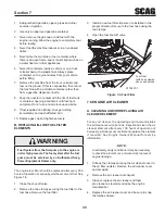
Страница 37: ...raulic System 7 3 A Checking Hydraulic Oil Level The hydraulic oil level should be checked after the first 10 hours of operation Thereafter check the oil after every 200 hours of machine operation or monthly whichever occurs first IMPORTANT If the oil level is consistently low check for leaks and correct immediately Wipe dirt and contaminants from around the 1 reservoir cap Remove the cap from the...

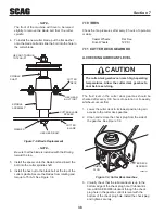
Страница 38: ...osive C Changing Hydraulic Oil Filter Element The hydraulic oil filter should be changed after every 500 hours of operation or annually whichever occurs first Remove the oil filter element and properly discard it 1 See Figure 7 3 Fill the new filter with clean oil and install the filter Hand tighten only Run the engine at idle speed with the speed control 2 lever in neutral for five minutes Check ...

Страница 39: ...ssure The fuel system after the fuel pump must be serviced by an Authorized Scag Power Equipment Dealer only The engine fuel filter should be replaced after every 500 hours of operation or annually whichever occurs first See Figure 7 6 Close the shut off valve 1 Remove the two clamps securing the fuel filter to the 2 fuel hose Remove the fuel filter Install a new fuel filter Be sure it is installe...

Страница 40: ...induce vomiting A Charging the Battery Refer to the battery charger s manual for specific instructions Under normal conditions the engine s alternator will have no problem keeping a charge on the battery If the battery has been completely discharged for a long period of time the alternator may not be able to recharge the battery and a battery charger will be required DO NOT charge a frozen battery...

Страница 41: ...ly yields a poor mowing job but slows the cutting speed of the mower and causes extra wear on the engine and the blade drive by pulling hard B Blade Sharpening NOTE If possible use a file to sharpen the blade Using a wheel grinder may burn the blade NOTE DO NOT sharpen the blades beyond 1 3 of the width of the blade See Figure 7 7 Sharpen the cutting edge at the same bevel as the 1 original See Fi...

Страница 42: ...7 10 Check the tire pressures after every 8 hours of operation or daily Caster Wheels Flat Free Drive Wheels 12 PSI Cutter Deck Gearbox 7 11 A Checking Lubricant Level Caution The cutter deck gearbox can reach high operating temperatures Allow the cutter deck gearbox to cool before servicing The fluid level in the cutter deck gearbox should be checked after every 100 hours of operation or bi weekl...

Страница 43: ... counterclockwise to remove Visually check the coolant level The coolant level 2 should be up to the bottom of the filler neck as shown in Figure 7 10 Add a mixture of coolant and soft water as needed NOTE Refer to the coolant manufacturer s instructions for the proper coolant mixture ratio Fill to Bottom of Filler Neck 030467 13 Coolant Level Figure 7 10 Replace the radiator cap Push down on the ...

Страница 44: ... wash any portion of the equipment while it is hot Do not wash the engine use compressed air After each use wash the mower and cutter deck 1 Use cold water and automotive cleaners Do not use pressure cleaners Do not spray electrical components 2 Use a mild soap solution or a vinyl rubber cleaner to 3 clean the seat Repair damaged metal surfaces using Scag touch 4 up paint available from your autho...

Страница 45: ...than Scag Power Equipment are not approved for use on this machine Scag approved attachments and accessories GC STT 61V p n 9060 GC STT CS61V p n 9064 Mulch Plate p n 9288 Hurricane Mulch p n 9285 STT Hitch p n 9242 STT Bumper p n 9256 STT Lights p n 9279 Tiger Striper p n 9269 Blade Buddy p n 9212 ILLUSTRATED PARTS LIST ...

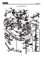
Страница 46: ... 20 53 28 52 24 58 24 52 73 66 32 13 68 55 55 29 58 2 3 23 3 11 50 13 46 60 49 67 24 35 48 9 16 19 15 27 26 12 82 51 23 23 36 37 44 39 43 42 38 45 41 34 62 22 40 37 18 10 1 5 7 6 8 STT EFI 2008 CD 14 29 12 30 28 31 25 31 21 22A 47 51 12 23 71 22A 13 72 74 28 29 13 26 57 75 76 77 78 79 80 81 83 84 85 70 ...

Страница 47: ... Hd 3 8 16 x 3 Bolt Hex Hd 3 8 16 x 1 1 2 Bolt Hex Hd 3 8 16 x 1 1 2 Grd 8 Spindle Assembly Spindle Shaft Seal Top Bearing Assembly Spindle Housing Spacer Outside Spacer Inside Seal Bottom Spindle Bushing Bottom Nut Special 1 1 16 18 Grease Fitting Relief Fitting Tapered Spindle 46 47 48 49 50 51 52 53 54 55 56 57 58 59 60 61 62 63 64 65 66 67 68 69 70 71 72 73 74 75 76 77 78 79 80 81 82 83 84 85 ...

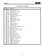
Страница 48: ...ECK CONTROLS STT2006CDC 21 19 37 42 4 6 14 10 42 5 2 3 35 23 41 38 32 34 30 7 27 33 40 41 28 28 24 26 41 40 CUTTER DECK 13 40 39 31 41 40 39 43 9 8 45 20 18 36 16 44 17 41 40 26 11 29 22 40 41 15 22 41 1 40 24 12 26 29 41 25 ...

Страница 49: ...16 Elastic Stop Slide Weldment Height Adjustment Spacer Decklift Pedal Pin Decklift Swivel Joint LH Swivel Joint RH Bellcrank Weldment LH Rear Bellcrank Weldment RH Rear Locknut 3 8 16 Center Lock Guide Short Guide Long Lockplate Decklift Deck Latch Incl 20 21 Bushing 502 I D Grip Deck Latch Spring Helper 61 72 Cutter Decks Only Foot Pedal Height Adjustment Nut Hex 5 8 11 Nut Hex Serr Flng 5 16 18...

Страница 50: ...PONENTS STT 2008 SMC 46 47 48 15 50 26 30 25 12 15 19 9 1 23 24 31 32 33 34 29 33 36 37 40 39 38 41 42 43 55 35 44 45 15 27 22 54 20 28 15 14 13 12 11 10 16 17 A 20 5 3 4 8 7 18 18 56 57 58 54 Suspension Seat 59 60 49 51 52 53 A A 6 ...

Страница 51: ...rr Flng 3 8 16 Screw Hex Serr Flng 3 8 16 x 1 Fender Weldment LH Foot Plate Nut Hex Elastic Stop 3 8 16 Bolt Hex Hd 3 8 16 x 1 Bolt Hex Hd 5 8 11 x 4 Bolt Hex Hd 5 8 11 x 4 1 4 Nut Hex Elastic Stop 5 8 11 Cap Grease Nut Hex Elastic Stop 1 0 14 Bearing w Race Plug 1 4 28 THD Form Extension Weldment Caster 61V LH Extension Weldment Caster 61V RH Seal 2 00 O D x 1 625 Bore Nut Hex Elastic Stop 1 2 13...

Страница 52: ...48 R Section 8 STT ROLL OVER PROTECTION SYSTEM WITH SUSPENSION SEAT STT 2007 FOLD ROPS 1 2 2 3 3 4 4 5 5 6 6 7 8 9 10 11 12 13 14 14 15 15 21 20 17 18 16 19 1 1 22 ...

Страница 53: ...483265 STT ROPS Accessory Incl all items below Bolt Hex Hd 1 2 13 x 4 1 2 Nut Center Lock 1 2 13 Bolt Hex Hd 7 16 20 x 1 Flatwasher 7 16 500 x 1 25 x 083 Retractable Seat Belt Bolt Hex Hd 3 8 16 x 2 Flatwasher 3 8 391 x 938 x 105 Sleeve Seat Base Mounting Nut Elastic Stop 3 8 16 Bolt Hex Hd 5 16 18 x 1 Bracket Seat Hold Down w Decal Spacer Seat Hold Down Nut Serr Flng 5 16 18 Flatwasher 1 2 562 x ...

Страница 54: ...40 3 47 46 47 43 42 4 41 45 59 53 8 54 72 5 6 64 63 62 7 52 55 9 60 61 10 11 56 52 12 15 65 58 52 14 13 12 20 17 45 18 66 19 67 45 56 21 57 58 52 22 18 23 24 49 50 69 25 26 27 28 29 30 36 35 34 33 32 31 68 48 51 38 71 73 70 39 53 45 46 52 44 45 45 45 37 73 16 45 52 74 75 76 ...

Страница 55: ...eck Drive Idler Arm Weldment Pump Drive Driveshaft Liquid Cooled Engine Set Screw 3 8 16 x 3 4 Torx Socket Screw 10 32 x 56 Flatwasher 3 8 391 x 938 x 105 Pin Rue Cotter 3 8 Dia Stud Anti Rotation Pump Mounting Plate Weld Liquid Cooled Nut Serr Flng 3 8 16 46 47 48 49 50 51 52 53 54 55 56 57 58 59 60 61 62 63 64 65 66 67 68 69 70 71 72 73 74 75 76 04019 02 04003 07 04021 22 04001 176 04063 06 0400...

Страница 56: ...52 R Section 8 ENGINE ATTACHING PARTS 31HP EFI KOHLER STT 2008 EAPKH EFI 8 9 6 10 13 FRAME REF PUMP MTG WELDMENT 11 1 3 5 2 10 12 10 12 10 12 13 14 17 15 16 7 4 18 19 20 21 22 23 24 ...

Страница 57: ...ohler Screen Weldment Radiator Kohler U Nut 1 4 20 Hour Meter Oil Drain Extension Engine Kohler 31HP EFI Aegis Available only through Kohler Bolt Hex Hd 3 8 16 x 1 Lockwasher 3 8 Spring Bolt Hex Hd 3 8 16 x 1 3 4 Nut Hex Elastic Stop 3 8 16 Bolt Hex Hd 3 8 16 x 1 1 4 Plate Engine Mounting Bolt Carriage 5 16 18 x 3 4 Nut Hex Serr Flng 5 16 18 Rear Cover o2 Sensor Available through Kohler Only Bolt ...

Страница 58: ...3 48 47 46 42 43 44 45 15 56 70 69 71 62 65 64 67 60 52 51 50 34 35 TO RH PUMP TO LH PUMP 37 36 27 28 35 33 78 34 31 30 29 8 9 32 13 B 9 B 25 18 72 49 55 54 75 26 5 68 66 37 36 61 59 74 7 20 13 14 22 14 39 16 24 38 63 24 38 12 79 22 21 A 40 38 80 77 45 2 76 4 3 6 6 81 5 82 5 53 34 58 5 C C 59 11 83 ...

Страница 59: ...be Control Link Liquid Cooled Engine Nut Hex 3 8 24 LH Thread Rod End Male 3 8 24 LH Thread Locknut 5 16 18 Elastic Stop Gas Damper Rod End 3 8 24 RH Female Grease Fitting Lever Parking Brake Incl 43 Grip Parking Brake Bolt Hex Hd 3 8 16 x 2 3 4 Swivel Joint 46 47 48 49 50 51 52 53 54 55 56 57 58 59 60 61 62 63 64 65 66 67 68 69 70 71 72 73 74 75 76 77 78 79 80 81 82 83 48343 04 04064 02 04062 01 ...

Страница 60: ...39 23 24 26 40 32 36 37 Z 34 25 35 21 31 33 9 30 30 57 56 54 7 4 4 3 44 45 50 46 51 53 52 49 5 4 4 5 42 34 25 35 55 18 8 20 19 6 22 41 27 28 29 30 38 Z 2 2 60 58 59 7 7 22 5 4 4 43 2 43 2 7 5 1 To Back Side of Reservoir Not Shown 10 62 63 11 15 To Engine 16 17 Fuel Return 64 15 14 14 13 14 10 48 47 14 12 12 65 65 65 65 66 66 ...

Страница 61: ...4 27 39 Elbow 90 Degree 38 Hose Bushing 56 Dia Viton Hose Clamp 0 69 Dia Hose 3 8 I D Pushlock Screw Phillips Head 1 4 20 Cap Fuel Tank Assembly Incl 16 17 65 66 Clamp Hose Elbow 90 Degree 7 8 14 THD Bushing 7 8 14 JIC x 3 4 16 O Ring Support Bracket Fuel Tank Nut 5 16 18 Serr Flng Bolt Carriage 1 4 20 x 3 4 Elbow 90 Degree Bushing 78 Dia Viton Strap Hydraulic Tank Support Bracket Hydraulic Tank H...

Страница 62: ... 8 BDP 16A HYDRAULIC PUMP ASSEMBLY WITH COOLING FAN OR OR PORT A SIDE PORT B SIDE Overhaul Seal Kit 1 2 3 4 5 6 7 8 9 10 11 12 13 14 15 16 17 17 18 19 20 20 21 21 22 23 24 25 26 27 28 29 30 31 32 33 34 35 36 37 27 ...

Страница 63: ...51348 HG52016 HG52014 HG51348 HG44809 HG52059 Overhaul Seal Kit Valve Plate Cylinder Block Kit 16cc Thrust Ball Bearing Assembly Variable Swashplate Slot Guide Trunnion Arm Block Spring Block Thrust Washer Shaft Ball Bearing Spacer Retaining Ring Seal Kit Pump Shaft keyed thru taper Housing Kit Trunnion Seal Kit Pin O Ring Straight Thread Plug Shock Valve Kit 031 Orifice Shock Valve Kit 024 Orific...

Страница 64: ...CTRICAL SYSTEM 31HP EFI KOHLER S C A G P O W E R E Q U IP M E N T 21 28 1 3 4 5 6 13 17 STT2008 ESKH EFI 10 11 17 18 15 14 20 22 23 24 25 26 28 29 30 14 15 9 10 11 8 B B 7 15 14 16 A 31 18 A C C 12 32 34 20 33 35 36 37 2 ...

Страница 65: ... 32 Lockwasher 5 8 Internal Instrument Panel Top w Decals Key Switch Switch PTO Relay Lockwasher 10 External Tooth Nut Hex 10 32 Water Temp Gauge Base Instrument Panel Lockwasher 1 4 Bolt Hex Hd 1 4 20 x 3 4 U Nut 1 4 20 Throttle Controls Screw Phillips Washer Head 10 32 x 1 2 Switch Interlock Seat Bolt Hex Hd 1 4 20 x 1 2 Cable Battery Red Nut Hex 1 4 20 Cable Battery Black Clamp Cable 1 2 I D Cl...

Страница 66: ... F R 11 482508 PULL OUT TO ENGAGE ON START PUSH IN TO DISENGAGE OFF MOWER DECk Heavy Duty Commercial 481971 10 22 CHECk ENGINE LIGHT 482984 SLOW FAST 23 25 MANUFACTURED UNDER ONE OR MORE OF THE FOLLOWING PATENTS 4 487 006 4 885 903 4 920 733 4 967 543 4 991 382 4 998 948 5 042 239 5 117 617 5 133 176 5 826 416 5 832 708 5 865 018 6 192 666 6 766 633 6 892 519 6 996 962 7 065 946 7 197 863 PATENTS ...

Страница 67: ...483158 483425 461982 Decal Danger Spinning Blades Decal Warning Rotating Blades Decal 61 Velocity Plus Decal Fuel Tank Decal Patents Decal Traction Control Decal Heavy Duty Commercial Decal Metalcraft Made In USA Decal Belt Cover Decal Warning Seat Hold Down Decal Instrument Panel Upper Decal Seat Replacement Decal Cutting Height Lower Decal Start Drive Procedure Decal Seat Support Decal Turf Tige...

Страница 68: ...ENOID STARTER B FUEL PUMP ENGINE DIAGNOSTIC LIGHT POS NEG ENGINE PLUG PINK BROWN RED W WHITE STRIPE GRN W WHT STRIPE GRN W BLK STRIPE LIGHT BLUE BLUE BLACK RED RED RED RED RED RED RED RED RED RED RED RED RED RED RED RED RED BLACK BLACK BLACK BLACK BLACK BLACK BLACK BLACK BLACK WHITE W BLK STRIPE WHITE W BLK STRIPE WHITE W BLK STRIPE ORANGE ORANGE BROWN RED W WHITE STRIPE PINK BLACK W ORANGE STRIPE...

Страница 69: ... and the expense of returning it to the owner after repair will be paid for by the owner Scag s responsibility is limited to making the required repairs and no claim of breach of warranty shall be cause for cancellation or rescission of the contract of sale of any Scag mower This warranty does not cover any mower that has been subject to misuse neglect negligence or accident or that has been opera...

Страница 70: ... propietario después de la reparación estarán a cargo del propietario La responsabilidad de Scag se limita a la realización de las reparaciones requeridas y ninguna reclamación por incumplimiento de las obligaciones de garantía será causa de cancelación o revocación del contrato de venta del cortacésped Scag Esta garantía no cubre ningún cortacésped que haya sido sometido a uso indebido descuido n...

Страница 71: ...dor Scag si requiere ajustar o reemplazar la correa 3 Coloque la tapa del radiador Presione la tapa hacia abajo y gírela en el sentido del reloj hasta que se detenga NOTA El sistema refrigeración debe ser purgado y el refrigerante debe ser reemplazado cada 500 horas de operación o cada año Consulte con su distribuidor Scag para información sobre el adecuado reemplazo del refrigerante B Limpieza de...

Страница 72: ...el del refrigerante El nivel de refrigerante debe llegar hasta el fondo del orificio de relleno como se muestra en la Figura 7 10 NOTA Consulte las instrucciones del fabricante para saber la relación adecuada de la mezcla del refrigerante Para evitar quemaduras siempre permita que el motor se enfríe antes de retirar la tapa del radiador 7 10 LLANTAS Verifique las presiones de las llantas después d...

Страница 73: ...la herramienta opcional Blade Buddy N P 9212 para ayudarlo a asegurar las cuchillas de corte y quite la tuerca del perno de fijación de la cuchilla Quite la cuchilla de corte el perno y el espaciador del eje Figura 7 8 NOTA Para quitar el perno de la cuchilla del eje de corte se tendrá que levantar ligeramente la parte frontal de la máquina 4 Para instalar la nueva cuchilla de corte coloque la ara...

Страница 74: ... cable negativo al poste negativo de la batería 7 8 CORREAS DE TRANSMISIÓN Todas las correas de transmisión están cargadas por resortes y son auto tensionantes pero después de las primeras 2 4 8 y 10 horas de operación debe verificarse su correcta alineación y revisar su desgaste Después verifique las correas después de cada 40 horas de operación o semanalmente lo que ocurra primero 7 9 CUCHILLAS ...

Страница 75: ...otor 1 Desenganche las abrazaderas que aseguran la cubierta del filtro de aire a la cámara del filtro de aire Quite la cubierta del filtro de aire y déjela a un costado 2 Quite el filtro de aire e inspecciónelo 3 Limpie o reemplace el filtro de aire como recomienda el fabricante del motor 7 7 BATERÍA Las baterías plomo ácido producen gases inflamables y explosivos Para evitar lesiones personales a...

Страница 76: ...mucho cuidado al manipular gasolina La gasolina es extremadamente inflamable y los vapores son explosivos 1 Apague todos los cigarrillos puros pipas y otras fuentes de ignición 2 Use solamente un recipiente aprobado para gasolina 3 Nunca retire la tapa de la gasolina ni agregue combustible con el motor en funcionamiento Permita que el motor se enfríe antes de abastecerlo de combustible 4 Nunca aba...

Страница 77: ...ador Si es necesario agregue aceite para motor SAE 20W50 7 4 ACEITE DEL MOTOR A Verificación del nivel de aceite del cárter El nivel del aceite del motor se debe verificar después de cada 8 horas de operación o diariamente como se indica en el manual del operador del motor proporcionado con este cortacésped B Cambio de aceite del cárter Después de las 5 primeras horas de operación cambie el aceite...

Страница 78: ... se debe cambiar cada 500 horas o en forma anual lo que ocurra primero El aceite también se debe cambiar si se ha vuelto de color negro o lechoso Un color negro y o un olor rancio indican generalmente un posible recalentamiento del aceite y un color lechoso indica habitualmente la presencia de agua NOTA El aceite hidráulico se debe cambiar si se nota la presencia de agua o se percibe un olor ranci...

Страница 79: ...ES DE GRASA DE LUBRICACIÓN LUBRICANTE INTERVALO T GRASA BLANCA DE LITIO MP 2125 40 HORAS SEMANALMENTE GRASA DE CHASIS 100 HORAS CADA DOS MESES GRASA DE CHASIS 200 HORAS MENSUALMENTE 3 1 5 4 6 2 GRASA DE CHASIS 500 HORAS ANUALMENTE STT EFI Grease Points 1 7 4 8 2 9 3 8 ...

Страница 80: ...4 4 Brazos de empuje de plataforma de corte 100 horas cada dos semanas Grasa de chasis 2 5 Eje PTO 40 horas semanalmente Grasa blanca de litio MP 2125 1 6 Eje de la plataforma de corte 40 horas semanalmente Grasa blanca de litio MP 2125 3 7 Mango del freno 200 horas mensualmente Grasa de chasis 1 8 Uniones en U del eje motriz de 200 horas mensualmente Grasa de chasis 2 la plataforma de corte 9 Man...

Страница 81: ...ceite del motor y el filtro Verifique la correcta alineación de todas las correas Verifique que no haya fugas en las mangueras hidráulicas Tenga mucho cuidado al verificar las mangueras hidráulicas Vea el párrafo 2 5 Verifique el nivel del refrigerante Kawasaki y Briggs Verifique el nivel de aceite del motor Limpie el cortacésped Verifique el estado de las cuchillas Aplique grasa a las conexiones ...

Страница 82: ... Coloque la plataforma de corte en posición de transporte 2 Quite los accesorios que aseguran el deflector de corte personalizado a la plataforma de corte NOTA La ubicación de los accesorios usados en las ilustraciones es sólo para referencia La ubicación de los accesorios puede variar de acuerdo con el tamaño de la plataforma de corte Figura 6 9 Ajuste del deflector de corte personalizado 3 Mueva...

Страница 83: ...la medida no se encuentra en 3 puede realizarse un ajuste utilizando la varilla de control de altura de la plataforma Vea la Figura 6 7 Ajuste del deflector de corte personalizado NOTA Si se tuvo que realizar un ajuste asegúrese que la plataforma de corte se pueda bloquear fácilmente en la posición de transporte 1 4 TOPE DE LA PLATAFORMA 390S0175 1 SP El deflector de corte personalizado está diseñ...

Страница 84: ...ea la Figura 6 6 gire las varillas de ajuste hasta que se alcance la inclinación adecuada en los lados derecho e izquierdo de la plataforma de corte Apriete ambas tuercas de bloqueo NOTA Para evitar la oscilación de la plataforma de corte las cuatro cadenas suspendidas de la plataforma de corte deben estar tensionadas Si las cuatro cadenas no están bajo tensión y la plataforma oscila debe reajusta...

Страница 85: ... 24 2 Si a máxima velocidad el cortacésped se tira a la izquierda es una indicación de que la rueda derecha gira más rápido que la izquierda Para ajustar esta condición proceda de la manera siguiente A Detenga la máquina y coloque las palancas de control de dirección en la posición neutral Afloje las tuercas de bloqueo que aseguran las juntas de rótula en cada extremo de la varilla de control de d...

Страница 86: ... hasta que la rueda motriz gire hacia adelante Gire la varilla en sentido contrario hasta que la rueda motriz deje de moverse Gire la varilla 1 2 vuelta adicional Vea la Figura 6 3 5 Apriete las contratuercas y repita el proceso para la rueda izquierda Vea la Figura 6 4 6 Accione las palancas de control de dirección hacia adelante y en reversa y regréselas a la posición neutral 7 Compruebe que las...

Страница 87: ...freno y girando la varilla hasta que se alcance la distancia adecuada Vea la Figura 6 1 Apriete las contratuercas 4 Con el freno en la posición accionada revise la compresión del resorte entre las dos arandelas planas al lado izquierdo de la máquina La distancia deberá ser de 1 7 16 Vea la Figura 6 2 5 Si la distancia no coincide con la medida especificada afloje la contratuerca en el extremo fina...

Страница 88: ...iado alta Disminuya la velocidad para ajustarse a las condiciones del terreno Césped mojado Corte el césped una vez que se seque Corte lateral Cresta en el centro de la trayectoria de corte Cuchillas mal montadas disparejas Ajuste la inclinación y el nivel Cuchilla doblada Reemplace la cuchilla Falla del eje interno Consulte con su distribuidor Scag autorizado Montaje incorrecto del eje Consulte c...

Страница 89: ... el terreno aumentar la altura de la plataforma de corte y o cambiar la dirección del corte Terreno disparejo Corte disparejo en terreno plano Apariencia baja y alta ondulada corte volado o perfil irregular Levantador de la cuchilla desgastado Reemplace la cuchilla Cuchilla montada invertida Monte la cuchilla con el filo hacia el terreno Césped acumulado debajo de la plataforma de corte Limpie la ...

Страница 90: ...s o desgastadas Afile las cuchillas Afilado incorrecto de las cuchillas Afile las cuchillas Bajas revoluciones rpm del motor Correa patinando Ajuste la tensión de la correa Césped acumulado debajo de la plataforma de corte Limpie la parte de abajo de la plataforma Velocidad demasiado alta Disminuya la velocidad para ajustarse a las condiciones del terreno Césped mojado Corte el césped una vez que ...

Страница 91: ...sición de operador lleve l as palancas de dirección fuera de la posición neutral de bloqueo y verifique que ambas palancas estén niveladas antes de operar Figura 4 8 Ajuste de las palancas de dirección PERILLA DE TENSIÓN PERILLA DE TENSIÓN PALANCA DE ROTACIÓN 4 15 Ajuste de las palancas de dirección 1 Coloque el asiento en la posición deseada 2 Al encontrarse en la posición de operador con el moto...

Страница 92: ...mo resultado una mala apariencia del césped y requiriendo potencia adicional del motor 2 La tolva de descarga no debe quitarse y debe mantenerse en su posición más baja para desviar hacia abajo el césped cortado y cualquier objeto que se encuentre sobre el mismo Dirija la descarga lateral lejos de aceras o de calles para minimizar la limpieza de los recortes de césped Cuándo corte cerca de obstácu...

Страница 93: ...carse o perder el control no arranque ni se detenga repentinamente evite giros innecesarios y desplácese a baja velocidad Si las llantas pierden tracción desconecte las cuchillas y baje lentamente la pendiente 3 Evite arranques repentinos al subir una cuesta Los arranques repentinos pueden causar que la máquina se incline hacia atrás 4 Puede producirse una pérdida de tracción al desplazarse bajand...

Страница 94: ...e Cuanto más se permita al control desplazarse hacia adelante más rápido girará el cortacésped a la izquierda Para dirigirse a la derecha mientras se desplaza en reversa permita que la palanca derecha de dirección se mueva hacia adelante Cuanto más se permita al control PRECAUCIÓN PRECAUCIÓN desplazarse hacia adelante más rápido girará el cortacésped a la derecha Para detener el desplazamiento en ...

Страница 95: ...es hidrostáticas debe practicar las operaciones de conducción y velocidad en el terreno en un área abierta lejos de edificios cercas u obstrucciones Practique hasta que se sienta cómodo con el manejo de la máquina antes de tratar de cortar Aprenda la operación en terreno plano antes de operar en pendientes IMPORTANTE Comience practicando a baja velocidad y desplazándose lentamente hacia adelante A...

Страница 96: ...e de elevación de plataforma Figura 4 1 Usada para levantar y bajar la plataforma de corte 13 Ajuste de la altura de corte Figura 4 1 Usado para poner la plataforma de corte en la altura de corte deseada 14 Palanca de liberación de la plataforma Figura 4 1 Usada para trabar la plataforma de corte en la Figura 4 2 Control de válvula de descarga posición de transporte Para corte normal empuje el ped...

Страница 97: ...a 4 1 Controles e Instrumentos de control horario F CONTROL IZQUIERDO DE DIRECCIÓN INTERRUPTOR DE LA PLATAFORMA DEL CORTACÉSPED INTERRUPTOR DE ENCENDIDO MEDIDOR DE COMBUSTIBLE VÁLVULA DE DESCARGA VÁLVULA DE DESCARGA FUSIBLES CONTROL DE ACELERACIÓN DEL MOTOR CONTROL DERECHO DE DIRECCIÓN ELEVACIÓN DE LA PLATAFORMA LIBERACIÓN DE LA PLATAFORMA 2008 STT EFI CHMI CONTROL DEL FRENO DE ESTACIONAMIENTO AJU...

Страница 98: ...13x 5 00 cuatro capas 52 13 X 6 00 cuatro capas 61 72 Ejes Servicio pesado 1 1 8 en la parte superior cuerpo fundido rodamiento de rodillos cónicos bajo mantenimiento con conexión de grasa en la parte superior y cabezal móvil de alivio de exceso de grasa Poleas del eje Acero partido con cubos cónicos de fácil desmontaje Correas de la plataforma de corte Sección B de Kevlar Auto ajustado auto apret...

Страница 99: ...os Amperímetro Interruptor de encendido Acelerador Estrangulación manual Interruptor BBC Fusibles y Módulo de arranque de seguridad Indicador de Temperatura Fusibles Dos 2 de 20 Amp 3 3 TRACTOR Sistema de transmisión Transmisión hidráulica con dos bombas de desplazamiento variable y dos motores de hierro fundido y alto torque Bombas hidrostáticas Dos bombas Hydro Gear BDP 16A con válvulas de desca...

Страница 100: ... Y DE SEGURIDAD 390S0150G 481568 F R 483397 483406 483407 483402 483398 483407 483397 483411 483425 483429 483300 483402 INSTALE LA CUBIERTA DE LA CORREA ANTES DE OPERAR LA MÁQUINA LEA EL MANUAL DEL OPERADOR ADVERTENCIA ADELANTE REVERSA 482710 ...

Страница 101: ... césped hojas exceso de grasa aceite y suciedad 7 Estacione la máquina en terreno plano y accione el freno de estacionamiento 8 NUNCA permita que personal sin entrenamiento dé servicio a la máquina 11 Use soportes de gato para apoyar componentes cuando sea necesario 12 Libere cuidadosamente la presión de los componentes que tengan energía almacenada 13 Permita que el motor se enfríe antes de almac...

Страница 102: ...n de seguridad puede ocasionar lesiones graves o la muerte 3 Revise la hebilla y el seguro para verificar su correcto funcionamiento y determine si la placa de cierre está excesivamente gastada deformada o si la hebilla está dañada o agrietada Vea la Figura 2 3 Reduzca la velocidad al girar o al operar en pendientes o en superficies húmedas o resbaladizas Permita una distancia adicional para deten...

Страница 103: ... levantar la barra contra vuelco suba la barra hasta la posición vertical 5 Instale los dos 2 pines de bloqueo a través del agujero asegúrelos con los dos 2 pasadores de chaveta de las horquillas y apriete las perillas de tensión Vea la Figura 2 2 Quite el cinturón de seguridad del soporte de sujeción No existe protección contra vuelco cuando la barra contra vuelco está en posición baja Baje la ba...

Страница 104: ...eversa a menos que sea absolutamente necesario y sólo después de observar toda el área detrás del cortacésped Si debe cortar en reversa mantenga la vista constantemente hacia la parte posterior de la máquina y corte lentamente 9 NO gire muy repentinamente Tenga cuidado al retroceder 10 Desconecte la potencia a la plataforma de corte antes de cruzar carreteras caminos o caminos de grava 11 Corte só...

Страница 105: ...able llevar gafas de seguridad zapatos de seguridad y un casco pues es requerido por algunos reglamentos locales y normas del seguro NOTA ADVERTENCIA ADVERTENCIA ADVERTENCIA 12 NO agregue combustible a un motor en operación ni a un motor caliente Permita que el motor se enfríe por varios minutos antes de agregar el combustible Nunca llene combustible bajo techo ni en un remolque cerrado 13 Manteng...

Страница 106: ...les lesiones o la muerte lea detalladamente el mensaje Cerciórese de entender completamente las causas que pueden ocasionar lesiones o la muerte Palabra de señalización Es una palabra distintiva que se encuentra en las calcomanías de seguridad del equipo y a través de este manual para alertar sobre la existencia y el grado de una condición de peligro La palabra de señalización DANGER PELIGRO La pa...

Страница 107: ...lo básico Elemento cortante Desconectar Continuamente variable Lineal Lea el manual del operador Mantenga alejados a los curiosos Punto de contacto 481039S SÍMBOLO DESCRIPCIÓN SÍMBOLO DESCRIPCIÓN Horómetro Horas de operación transcurridas Peligro de objetos lanzados ...

Страница 108: ...ria 48071S Freno de estacionamiento WARNING FALLING HAZARD USE ONLY SCAG APPROVED RIDING ATTACHMENTS SEE OPERATOR S MANUAL 481109 Riesgo de caída Peligro de objetos lanzados Durante la instalación el asiento debe instalarse debajo de su soporte de sujeción No asegurar el asiento debajo de su soporte de sujeción puede ocasionar lesiones graves o la muerte en caso de volcadura ...

Страница 109: ...plazamiento hacia adelante 1 3 SERVICIO AL MOTOR Y A LOS COMPONENTES DEL TREN DE TRANSMISIÓN Los detalles sobre servicio y reparación del motor las bombas hidráulicas y cajas de cambios no están cubiertos en este manual sólo se proporcionan instrucciones de mantenimiento de rutina y de servicio general Para dar servicio a estos componentes durante el período de garantía limitada es importante cont...

Страница 110: ... Cuchillas de corte 36 7 10 Llantas 38 7 11 Caja de cambios de la plataforma de corte 38 7 12 Sistema de refrigeración Kawasaki 38 7 13 Cuerpo plataforma tolva y tapicería 39 Sección 8 Piezas de repuesto Plataforma de corte STT61V 38 39 Controles de plataforma de corte 40 41 Componentes de láminas metálicas 42 43 Sistema de protección contra vuelco STT con asiento de suspensión 44 45 Componentes d...

Страница 111: ...Instrucciones de operación 4 1 Identificación de controles e instrumentos 13 4 2 Sistema de bloqueo de seguridad 14 4 3 Procedimientos de arranque inicial 15 4 4 Arranque del motor 15 4 5 Desplazamiento en el terreno y dirección 15 4 6 Conexión de la transmisión de plataforma 16 4 7 Operación en una cuesta 17 4 8 Estacionamiento del cortacésped 17 4 9 Después de la operación 17 4 10 Retiro del mat...

Страница 112: ...mente la de la tolva de descarga de césped Antes de realizar cualquier mantenimiento o servicio detenga la máquina y quite el cable de la bujía y la llave de encendido Si un mecanismo se atasca detenga el motor antes de limpiar Mantenga las manos los pies y la ropa lejos de las partes móviles Lea este manual completamente así como cualquier otro manual proporcionado con su cortacésped Mantenga a o...

Страница 113: ...R EN EL MANTENIMIENTO Y LOS PROCEDIMIENTOS DE AJUSTE A FIN DE MANTENER SU CORTACÉSPED TRABAJANDO A LA MÁXIMA EFICIENCIA LOS MODELOS ESPECÍFICOS CUBIERTOS POR ESTE MANUAL ESTÁN INDICADOS EN LA CUBIERTA INTERIOR ANTES DE OPERAR SU MÁQUINA LEA TODA LA INFORMACIÓN INCLUIDA PARTE Nº 03242 IMPRESO EN ENERO DE 2008 IMPRESO EN EE UU 2008 SCAG POWER EQUIPMENT DIVISION OF METALCRAFT OF MAYVILLE INC ...

Отзывы: