©2021 Lowell Manufacturing Co. | X-Rev.10-21-21
1
UPS-XBPA Series: Expansion Battery Pack
Models: UPS-XBPA-36, UPS-XBPA-36E, UPS-XBPA-48, UPS-XBPA-72
User & Installation Manual
power
TM
Страница 1: ...2021 Lowell Manufacturing Co X Rev 10 21 21 1 UPS XBPA Series Expansion Battery Pack Models UPS XBPA 36 UPS XBPA 36E UPS XBPA 48 UPS XBPA 72 User Installation Manual power TM...
Страница 2: ...1 2 Table of Contents 1 Important Safety Warnings 3 2 Product Overview Setup 4 a Rack installation 5 b Tower installation 6 c Connecting UPS with another Battery Box 6 3 Type of Battery Required 7 4 B...
Страница 3: ...deliberately or accidentally inserted into the battery box enclosure The battery will discharge naturally if the system is unused for a period It should be recharged every 2 3 months if unused If thi...
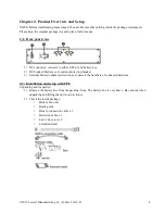
Страница 4: ...UPS or 2nd battery box 2 DC breaker Battery over current protection breaker 3 External battery numbers detection port detects the numbers of connected batteries 2 2 Installation and setup with UPS Un...
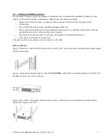
Страница 5: ...in accordance with the unit s working specifications to avoid overheat and excessive moisture Do not place the unit in a dusty or corrosive environment or near flammable objects This unit is not desi...
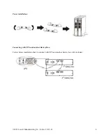
Страница 6: ...2021 Lowell Manufacturing Co X Rev 10 21 21 6 Tower installation Connecting with UPS and another Battery Box Follow below installation chart to connect with UPS and another battery box with included...
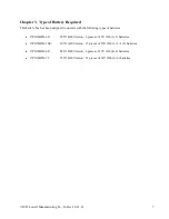
Страница 7: ...gned to operate with the following types of batteries UPS XBPA 36 36V 18Ah Version 6 pieces of 12V 9Ah 3 3 batteries UPS XBPA 36E 36V 36Ah Version 12 pieces of 12V 9Ah 3 3 3 3 batteries UPS XBPA 48 48...
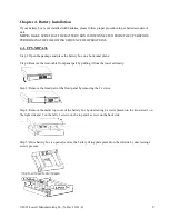
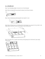
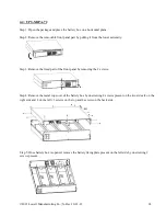
Страница 8: ...1 Open the package and place the battery box on a horizontal plane Step 2 Remove the removable front panel part by pulling it from the lower extremity Step 3 Remove the fixed part of the front panel b...
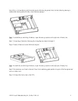
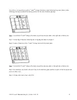
Страница 9: ...the same procedure on the right side of battery box Step 7 Connecting all batteries following the wiring diagram shown in chapter 5 Step 8 Secure all batteries inside with the metal plate Note To ins...
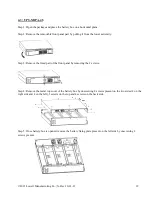
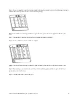
Страница 10: ...he lower extremity Step 3 Remove the fixed part of the front panel by removing the 2 screws Step 4 Remove the metal top cover of the battery box by unscrewing 8 screws present on the two sides 4 on th...
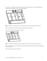
Страница 11: ...he same procedure on the right side of battery box Step 7 Connecting all batteries following the wiring diagram shown in chapter 5 Step 8 Secure all batteries of the 1st and 2nd strings inside with th...
Страница 12: ...e lower extremity Step 3 Remove the fixed part of the front panel by removing the 2 screws Step 4 Remove the metal top cover of the battery box by unscrewing 8 screws present on the two sides 4 on the...
Страница 13: ...the same procedure on the right side of battery box Step 7 Connecting all batteries following the wiring diagram shown in chapter 5 Step 8 Secure all batteries inside with the metal plate Note To ins...
Страница 14: ...e lower extremity Step 3 Remove the fixed part of the front panel by removing the 2 screws Step 4 Remove the metal top cover of the battery box by unscrewing 8 screws present on the two sides 4 on the...
Страница 15: ...the same procedure on the right side of battery box Step 7 Connecting all batteries following the wiring diagram shown in chapter 5 Step 8 Secure all batteries inside with the metal plate Note To ins...
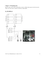
Страница 16: ...Rev 10 21 21 16 Chapter 5 Wiring Diagrams Note The cable connection from external battery connector to PCB is already present inside the battery box All the other cable connection should be followed b...
Страница 17: ...2021 Lowell Manufacturing Co X Rev 10 21 21 17 5 2 UPS XBPA 36E...
Страница 18: ...2021 Lowell Manufacturing Co X Rev 10 21 21 18 5 3 UPS XBPA 48...
Страница 19: ...2021 Lowell Manufacturing Co X Rev 10 21 21 19 5 4 UPS XBPA 72...