Lovato RGAM40 Скачать руководство пользователя страница 1


                                                                                                                                                                                p. 1 / 24


RGAM40                         

            RGAM40 

RGAM41                                     RGAM41 
RGAM42                                     RGAM42 

 Контроллер генератора с                       Gen-set controller 
 функцией автоматического                    with AMF function  

запуска                                                         (Automatic Mains Failure) 


 РУКОВОДСТВО ПО ЭКСПЛУАТАЦИИ


INSTRUCTIONS MANUAL


Введение 

При разработке данного устройства учитывалась простота операций с 
широким набором функций. Графический жидкокристаллический 
экран  с расширенным пользовательским интерфейсом и вкладками 
входов-выходов позволяют применять RGAM4x  для управления 
пуском различных генераторов. 


Introduction 

This device has been designed to integrate the maximum operation 
easiness with a wide selection of functions. The graphic LCD display 
allows an advanced user interface, and the input-outputs  endowment 
makes the RGAM4x suitable for a wide range of gen-set applications. 
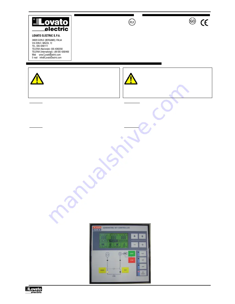


Описание  


Контроль генератора с функцией автоматического запуска (AMF) 


Входы измерения трех фаз сети  


Вход измерения трехфазной сети генератора  


Универсальное питание 12-24Vdc 


LCD графический экран 128x64 пикселей с подсветкой 


Текст на 5 языках: Английский-Итальянский-Французский-
Португальский-Испанский 


9 LED индикаторов для отображения режимов работы 


Клавиатура с 12 кнопками. 


Порт связи RS-232 для программирования и удаленного 
управления.  


3 аналоговых входа для датчиков  


8 программируемых цифровых входа 


7 релейных выходов, программируемых 


Вход скорости вращения вала или датчика магнитных импульсов


Интерфейс связи RS485 для удаленного управления (версия 
RGAM41)


Интерфейс связи CANbus для управления двигателем            
(версия RGAM42) 


Часы- календарь с источником питания (версии RGAM41 и 
RGAM42) 


Description 


Gen-set control with automatic management of the AMF (Automatic 
Mains Failure) function 


Three-phase mains measurement input  


Three-phase generator  measurement input  


12-24Vdc universal power supply unit 


Graphic LCD display,  128x64 pixels, backlighted 


Texts in 5 languages: English-Italian-French-Porttuguese-Spanish 


9 LEDs for status and operating mode indication 


12-key membrane keyboard 


RS232 communication interface for set-up, remote control and 
supervision  


3 analog inputs for resistive sensors 


8 programmable digital inputs 


7 relay outputs, all programmable 


Engine speed input for W or magnetic pick-up signals


RS485 communication interface for  remote control and supervision  


(RGAM41 version)


CANbus communication interface for engine ECU control 


      (RGAM42 version)


Real time clock with back-up capacitors (RGAM41 and RGAM42 
versions)


I 2

24

RU

G

B

 0

607


Внимание!

Технические описания и данные, 

приведенные в данном руководстве, являются 

наиболее полными на данный момент, но могут быть 
изменены без предупреждения. Установка прибора 

производится специально обученным персоналом, и в 
полном соответствии с требованиям существующих 

стандартов и нормативов во избежание несчастных 
случаев


WARNING!

 This equipment is to be installed by qualified 

personnel, complying to current standards, to avoid damages or 

safety hazards. Products illustrated herein are subject to alteration 
and changes without prior notice. Technical data and descriptions 

in the documentation are accurate, to the best of our knowledge, 
but no liabilities for errors, omissions or contingencies arising 
therefrom are accepted. 

Содержание RGAM40

Страница 1: ...ния двигателем версия RGAM42 Часы календарь с источником питания версии RGAM41 и RGAM42 Description Gen set control with automatic management of the AMF Automatic Mains Failure function Three phase mains measurement input Three phase generator measurement input 12 24Vdc universal power supply unit Graphic LCD display 128x64 pixels backlighted Texts in 5 languages English Italian French Porttuguese...

Страница 2: ...йных сообщений Если ситуация приведшая к возникновению аварийного состояния системы аларм не прекратилась сброс аварийного сообщения невозможен Modo MAN ручной режим работы В ручном режиме работы запуск и остановка двигателя производится нажатием клавиш START и STOP а переключение питания потребителя на сеть или на генератор нажатием клавиш MAINS и GEN Время запуска может быть увеличено посредство...

Страница 3: ...s Also used to enter a deeper level menu Key STOP is used to exit cancel answer No also used to Exit to a higher level menu Key OFF RESET stores and quit Menu Icons Clock setting Command menu Parameters Setup Custom Setup Меню команд Выберите нужную команду Нажмите кнопку START для выполнения Необходимо быстро подтвердить выбор нажав START еще раз либо отменить STOP В пользовательском меню команда...

Страница 4: ...age with data alarms measurements etc This page can contain details convenient to the user such as customer s name date of panel or genset manufacture set up file name serial number of the electric panel or genset main technical data and so on Техническая информация Программируемые цифровые входы и выходы Все выходы и часть входов устройства по умолчанию связана с определенной функцией прибора см ...

Страница 5: ...he previous menu Аналоговые входы Если двигатель оборудован аналоговыми датчиками проверьте соответствие датчика запрограммированному в подменю ENGINE CONTROL Установка параметров нового датчика осуществляется с помощью программного обеспечения В случае отсутствия или несоответствия датчика данный аналоговый вход должен быть блокирован Analog inputs of the sensors Check if the sensors mounted on t...

Страница 6: ...MENU 08 Не доступно MENU 09 Тест и обслуживание MENU 10 Порт связи MENU 11 Прочее MENU 12 Программируемые входы MENU 13 Программируемые выходы MENU 14 CANbus MENU 15 Таблица сигналов Установка часов Установки пользователя MENU LIST MENU 01 Utility MENU 02 General MENU 03 Battery MENU 04 Engine starting MENU 05 Engine control MENU 06 Mains control MENU 07 Generator control MENU 08 Generator protect...

Страница 7: ...eed P0210 Unit of measure of the analog sensors P0211 Unit of measure is the one programmed at parameter P0210 P0212 Interlock Time gap between MAINS relay opening and GEN relay closing and vice versa P0213 With contactor feedback control enabled after this time alarms A24 generator contactor fault to A23 mains contactor fault are output P0214 If ON at power on the instrument is always set to Rese...

Страница 8: ...tart up attempt during during which the engine running signal has not been detected and the next P0409 Pause between an interrupted start up and the next P0410 Energization time of the relay programmed with the decelerator function P0411 Time between disconnection of the load from the generator and stopping of the engine P0412 Energization time of the relay programmed with the stop magnet function...

Страница 9: ...IN MAX voltage hysteresys 3 0 0 0 5 0 P0607 Предел ассиметрии MAX 15 OFF 5 25 P0607 MAX asymmetry limit 15 OFF 5 25 P0608 Задержка сигнала ассиметрии MAX s 5 0 600 P0608 MAX asymmetry delay s 5 0 600 P0609 Предел частоты MAX 110 100 120 OFF P0609 MAX frequency limit 110 100 120 OFF P0610 Предел частоты MIN 90 OFF 80 100 P0610 MIN frequency limit 90 OFF 80 100 P0611 Задержка сигнала частоты MIN MAX...

Страница 10: ... device EXT generator controlled by an external device It is possiblee to use a programmable input with External generator control function connected to the external instrument P0714 Trip delay of alarms A27 and A28 referred to the trip thresholds for voltage outside limits set MENU 08 ЗАЩИТА ГЕНЕРАТОРА Поумол Пределы MENU 08 GENERATOR PROTECTION Default Range Р0801 номинальный ток генератора А OF...

Страница 11: ...mode in case of communication interruption OFF OFF ON P1001 Адрес серийного порта связи RS232 P1002 Скорость передачи порта связи RS232 P1003 AUTO автоматическое распознавание типа протокола связи либо ASCII либо Modbus RTU P ASCII установка протокола Lovato ASCII RTU установка протокола MODbus RTU P1004 Установка паритета порта связи RS232 P1005 Адрес серийного порта связи RS485 P1006 Скорость пе...

Страница 12: ...ched from the mains to the generator The load is returned to the mains on opening of the switching consent and the group performs the stop cycle on opening of the start input The EJP function is enabled only if the system is in automatic mode The safety measures and alarms function as usual EJP T The EJP T function is a simplified variant of the previous EJP where starting of the engine is control...

Страница 13: ...пользоват UA2 Сигналы пользоват UA3 Сигналы пользоват UA4 P12 1 1 P12 8 1 Selection of the function of the input selected see table below P12 1 2 P12 8 2 Selection of the type of contact NO normally open or NC normally closed P12 1 3 P12 8 3 Delay in closing of the contact on the input selected P12 1 4 P12 8 4 Delay in opening the contact on the input selected Functions input list Description Disa...

Страница 14: ...я на максимальное время установленное параметром P0415 Если двигатель запускается реле обесточивается как только напряжение на генераторе превысит пик параметра P0416 Рабочий режим воздушной заслонки также зависит от параметра P0418 Клапан насоса Реле воздушной заслонки активируется в тоже время что и реле заслонки газа только в течение первых попыток пуска Остается активировано на время установле...

Страница 15: ...t see table below column A Engine running see table below column B Engine failure see table below column C Low Fuel see table below column D Gen set ready Gen set in AUT without alarms Preheating valve Controls the preheating valve See P0423 and P0424 Topping up pump Controls the topping up pump See the related programmable input functions and parameters P0513 P0514 In OFF RESET mode the pump is a...

Страница 16: ...ne W pick up speed A21 неудачный старт X X X X X X A21 Starting failure A22 аварийная остановка X X X X X X A22 Emergency stop A23 непредвиденная остановка двигателя X X X X X X A23 Unexpected stop A24 неудачная остановка двигателя X X X X X X A24 Engine stop failure A25 низкая частота генератора X X X X X X X A25 Low generator frequency A26 высокая частота генератора X X X X X X A26 High generato...

Страница 17: ...окое напряжение генератора A28 High generator voltage A29 асимметрия фаз генератора A29 Generator asymmetry A30 короткое замыкание генератора A30 Generator short circuit A31 перегрузка генератора A31 Generator overload A32 срабатывание внешней защиты генератора A32 External generator protection tripping A33 неправильное чередование фаз генератора A33 Incorrect generator phases sequence A34 неправи...

Страница 18: ...latter case check correct connection A10 Fuel level lower then the set warning threshold A11 Fuel level lower then the set alarm threshold A12 Resistive fuel level sensor fault A13 Low fuel level Top up A14 A15 Battery voltage outside limits set Check battery charger or battery efficiency A16 The battery is unable to manage start up and power the system Check the charging system of the battery A17...

Страница 19: ...еста 30 Автотест активенTest autom Abilitato 31 Автотест деактивирован 32 Настройка 33 Установка параметров 34 Меню пользователя 35 Установка RTC 36 Клавиатура разблокирована 37 Клавиатура заблокирована 38 Журнал событий очищен 39 Доступ к меню команд 40 Начало удаленного управления 41 Конец удаленного управления 42 Входящий звонок модема 43 Линия модема закрыта 44 Звонок модема к ПК 45 Звонок мод...

Страница 20: ...voltage inputs Номинальное напряжение Ue макс 480VAC L L 277VAC L N Maximum rated voltage Ue 480VAC L L 277VAC L N Пределы измерения 50 576V L L 332VAC L N Measuring range 50 576V L L 332VAC L N Пределы частоты 45 65Hz 360 440Hz Frequency range 45 65Hz 360 440Hz Тип измерения TRMS Measuring method True RMS Сопротивление входа измерения 3 3M Measuring input impedance 3 3M Типы присоединения L1 L2 L...

Страница 21: ... Уровень загрязнения Класс 3 Maximum pollution degree 3 Категория перенапряжения 3 Overvoltage category 3 Категория измерения III Measurement category III Присоединения Connections Тип клемм Втычные Terminal type Plug in removable Сечение проводника min и max 0 2 2 5 mmq 24 12 AWG Cable cross section min max 0 2 2 5 mm 24 12 AWG Рабочее UL Сечение проводника min и max 0 75 2 5 mm 18 12 AWG UL Rati...

Страница 22: ... 22 24 Схемы присоединения Wiring diagrams Схема присоединения к трехфазной сети с генератором переменного тока Wiring diagram for three phase generating set with pre energised battery charger alternator ...

Страница 23: ...ение с генератором с системой постоянных магнитов Wiring for single phase generating set Wiring for generating set with permanent magnet battery charger alternator Присоединение для генератора с входом pick up Wiring for pick up input generating set C B REG ...

Страница 24: ...10 1 L2 10 2 L1 L1 L2 9 2 L3 9 3 6 5 3 6 6 8 6 7 6 6 DC VOLTAGE OUTPUT RELAYS 3 4 3 5 3 3 3 1 3 2 VOLTAGE FREE OUTPUT RELAYS 2 2 2 3 2 1 6 4 6 3 6 1 6 2 INPUTS DIGITAL 5 9 5 8 5 6 5 7 5 5 ANALOG INPUTS 8 2 8 4 8 3 8 6 8 5 L3 INPUTS Ie 5A L2 8 1 L1 VOLTAGE FREE OUTPUT RELAYS 1 5 1 4 1 3 1 2 1 1 12 24 V 5 2 5 3 5 4 5 1 4 2 DETECT START 4 1 9 1 MAINS SG 7 1 VOLTAGE INPUTS GENERATOR TR 7 4 B 7 2 A 7 3...

Отзывы: