LOOP LP-2150
&
LP-2151
ALL-IN-ONE PC
CHASSIS INTEGRATION WITH THE
GIGABYTE GA-Q87TN
DESKTOP BOARD
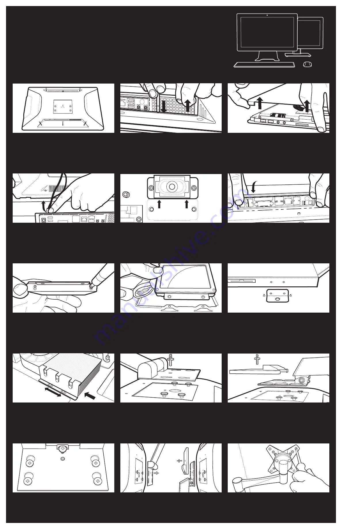
There are two screws at the “top” of the system and three at the
base that should be unfastened to enable the removal of the rear
cover.
1. Unfastening the Rear Cover Screws
Press a screwdriver down on the metal strip and pull the cover
upwards in the corner closest to the rear vent.
2. Lifting the Rear Cover
Lift the corner closest to the rear vent and the section close to
the card reader slot. Once the corner of the rear cover has been
lifted slightly, it should be possible to remove the cover. If a
desktop board is already installed, do not remove the cover until
Step 6 is complete.
3. Removing the Rear Cover
If the system has been configured previously, ensure that the
system fan is disconnected before complete removal of the
rear cover.
4. Disconnecting the System Fan Header
Move the internal speaker closest to the LVDS connection to
create more space when installing the desktop board and the
LVDS connector.
For 2.5” drives, locate the drive faster in the upper slot on the
drive bracket to prevent unnecessary pressure on the SATA Data
and Power Connector when installed into the chassis.
Orientate the bracket correctly and fasten the three screws to
keep the drive in position.
5. Moving the Internal Speaker
When inserting the IO shield, check that it is orientated correctly.
6. Inserting the IO Shield
7. Attach Drive to Bracket
8. Drive Bracket Installation
Don’t lose the small bracket and screws that are used to attach
the ODD drive to the chassis.
Once the four fasteners are secure on the rear panel, place the
stand bracket in place and slide to align with the locking screw.
Please Note: If this system will be shipped, ensure that the stand is
properly removed, disassembled and packed properly for shipping.
Once the four fasteners are secure on the rear panel, place the
stand bracket in place and position the rear cover bracket correctly.
If attaching a VESA mount to the chassis, secure the chassis to the
VESA bracket by tightening the 4 fasteners.
9. ODD Drive Bracket and Screws
When installing the Intel® Thermal Solution, align the screws
correctly and confirm that the fan and heat sink are properly
aligned.
10. Installing the Intel® Thermal Solution
11. LP-2150 Stand Assembly
12. LP-2150T Stand Assembly
For both chassis ensure that the locking screw is properly
fastened, to keep the bracket in place.
13. Connecting the Stand
14. Preparing the Stand for Shipping
15. VESA Mount Option
LOOP LP-2150
-SPECIFIC INTEGRATION NOTES


