


COMPILER TECO/ATL
REG. CODE
1-5302-509
MODEL N°
50778
DATE OF ISSUE
10.06.99
REVISION
00
ENDORSED
DATE
10.06.99
61
XII
IGNITION
149
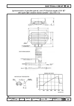
The technical specifications of the modules are similar for
engines LGW 523 and LGW 627. Despite this fact, different
types can be mounted since the programming maps can vary.
Make sure that the right one is installed in case of
replacement.
The spark lead curve is the same for both engines LGW 523
and LGW 627
Technical specifications of the ignition module
·
Spark produced regardless of a low idling rate
·
Power source voltage rating : from 5.6 Volts to 18 Volts; can
withstand 18 Volts for 1 hour of 24 Volts for 1 minute
·
Operating temperature : from -40° to +85° C.
·
Maximum power draw: 2.1 A at a low idling rate (<500 r/min) with 14.5 Volt power supply
·
Power draw before start-up: 50 mA ( current activation in the coil occurs after engine movement has been detected)
·
Protection against overtemperatures
·
Protection against short circuits
·
Ability to pilot coils with a 0.5
W
W
W
W
W
primary (primary resistance) and 7 mH inductance
·
Current limitation in the coil: 6 A
·
Coil disconnected from the power supply if the engine accidentally stops (with the ignition key inserted)
·
Protection against disconnection (accidental and intentional) of the high voltage wires from the coil and spark plugs
·
Solenoid cut-off monitoring output protected against short circuits
·
Fade-free current to primary of high voltage coil
The functionality test of the ignition module should be carried out by means of the relative instrument. The module should be
replaced if faults are discovered.
LGW 523 coil
The coil is powered by two wires.
The red one is constantly powered by the battery through 15-54.
The brown (or pale blue) wire is controlled by the module.
To charge the coil, the module is grounded by the second wire via an
internal contact: this allows current to circulate (regulated by the
module and no longer at 6 A) and the magnetic circuit of the coil to
charge.
The moment in which the spark must strike, the ground connection is
opened. This causes the voltage to rapidly rise on the secondary and
thus produce the spark.
At engine speed of less than 900 r/min, the coil is powered when the
lamination enters the sensor, to guarantee maximum energy during
the ignition phase.
At higher speeds, the module measures the time that elapses between two successive entries of the lamination, thus
evaluating the rotating speed of the engine.
The sparking point is chosen according to the rotating speed in a table measured by the module.
More precisely, the table gives the time that must be waited after the lamination has entered the sensor before the coil is
activated. The coil remains activated for 1.5 ms (0.0015 sec.) after which the spark is struck.
Since the coil activation point is determined by the module according to the rotation speed value measured during the
previous revolution, module calculations may involve an excessive delay in the coil activation instant in the case of repeated
accelerations and this may make the engine misfire.
To prevent this from happening, the spark is never given beyond the point the enabling lamination leaves the sensor even if
the delay time calculated by the module has not yet elapsed.
The coil can be checked by means of the instrument used to test the module.
Faulty coils must be replaced.
150
Code


