background image

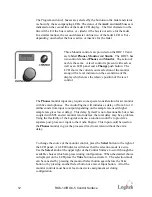
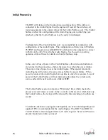
The Cue knob controls the volume of the local cue speaker
which has its own amplifier.  Cue audio is returned to the
Control Surface from the Audio Engine as digital data on the
Control Surface cable.  It is converted to analog at the Control
Surface.  The relative cue level is indicated by the vertical bar on 
the second line of the timer LCD display.

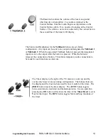
The Source and Destination for the  Talkback buttons are set during
configuration.  Any input can be sent to any output and designated as  Talkback 1
or Talkback 2.  When the associated Talkback button is pressed, the designated
input is sent to the output while the button is pressed.  When the button is
released, the connection is broken.  This allows temporary audio connections to
be made for such functions as intercom.

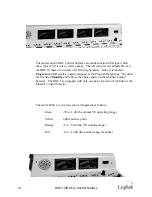
The Timer display to the right of the VU meters is count up  and the
events which reset it are set during configuration.  The buttons between
the display and the Cue knob are used for local control of the timer.  The
ZERO   button resets the timer display.  The  AUTO button toggles
between automatic reset/start and manual operation.  In auto operation
pressing any  ON button will activate the timer if the  Timer Reset is set to 
Yes for that input.  The  RUN  button toggles Start and Stop functions of
the timer.

Logitek Digital Consoles

ROC-10/ROC-5 Control Surface

13

Содержание ROC 10

Страница 1: ...ROC 10 and ROC 5 Digital Audio Consoles...

Страница 2: ...Systems Inc 5622 Edgemoor Drive Houston Texas 77081 Tel 713 664 4470 Fax 713 664 4479 Email help logitekaudio com Website www logitekaudio com Contents 1998 Logitek Electronic Systems Inc ii ROC 10 RO...

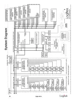
Страница 3: ...tion 7 Operation 9 Initial Power Up 15 Appendix 19 Control Surface Data Cable 19 Communications Controller GPI 21 Port 4 RS 232 23 Audio Engine AE32 Specifications 24 System Block Diagram 26 ROC 10 In...

Страница 4: ...This page is intentionally blank iv ROC 10 ROC 5 Control Surface...

Страница 5: ...ing mix minuses and all other traditional functions of consoles The Audio Engine erases the differences to the user between digital and analog sources or destinations The Audio Engine can accept digit...

Страница 6: ...nd Control Surface are boxed separately Each box contains a separate packing list showing the contents Verify that the contents of each box matches the packing list and report any discrepancies to Log...

Страница 7: ...d out so that the top of the tray flanges are flush with the top of the mounting surface This way the console will appear to sit flat on the table top The tray mounting flanges can be screwed to the t...

Страница 8: ...f the cable is 300 meters or 1000 feet These cables can be ordered through Logitek in the length you need Recommended wiring for this connection is Category 5 computer cable The ROC Console control su...

Страница 9: ...s Faders may also have click down cue switching by setting the Cue Inf function in the configuration software When the fader is brought to within 1 inch of the bottom of its travel the selected input...

Страница 10: ...ment buttons lens caps and LEDs are available from Logitek Part numbers are listed in the Appendix Mixer Pots are designed to feel to the operator like a traditional slider External control or auxilia...

Страница 11: ...s few of the Audio Engine inputs as you desire All faders must have at least one input assigned Remember that as inputs change any attributes attached to that input such as muting or machine starts wi...

Страница 12: ...The Audio Engine will introduce a delay of from 6 to 10 milliseconds from input to output depending on the sample rate used higher sample rate gives lower delay This delay by itself is not objectionab...

Страница 13: ...designated input is sent to the output while the button is pressed When the button is released the connection is broken This allows temporary audio connections to be made for such functions as interc...

Страница 14: ...ned as the Program Output bus The other set is labeled Monitor and follows the choice made on the Monitor Control Selector The ROC 5 is equipped with only one pair of meters which follows the Monitor...

Страница 15: ...e configuration software Separate definitions of outputs can have different reference levels set during configuration The digital output zero VU corresponds to 20 dBFS and cannot be changed Other mete...

Страница 16: ...ol Surface all switches and indicators are returned to the same state as before the power loss when the power returns The same is true of power loss at the Audio Engine When power returns the Audio En...

Страница 17: ...This page is intentionally blank Logitek Digital Consoles ROC 10 ROC 5 Control Surface 17...

Страница 18: ...This page is intentionally blank 18 ROC 10 ROC 5 Control Surface...

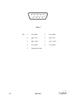
Страница 19: ...he male connector is shown Pinout is the same at both ends Port 3 has no Cue audio connection so pins 1 and 6 are not connected on this port and only two pairs are used All ports operate at 38 4 Kbps...

Страница 20: ...Port 3 Pin 1 no connect 6 no connect 2 pair 1 TX 7 pair 1 TX 3 pair 2 RX 8 pair 2 RX 4 no connect 9 no connect 5 enclosure ground 20 Appendix...

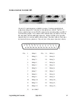
Страница 21: ...aximum and 500 milliamps maximum Higher currents will require the internal relays to switch an added outboard relay Interface cables in both cases are made with male connectors The rear view of the ma...

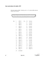
Страница 22: ...GPI In 3 22 Ground 4 GPI In 4 23 Ground 5 GPI In 5 24 Ground 6 GPI In 6 25 Ground 7 GPI In 7 26 Ground 8 GPI In 8 27 Ground 9 GPI In 9 28 Ground 10 GPI In 10 29 Ground 11 GPI In 11 30 Ground 12 GPI In...

Страница 23: ...ta bits 1 stop bit and even parity The cable uses a male connector at the Audio Engine and a female connector at the computer Wire pin 2 to pin 2 pin 3 to pin 3 and pin 5 to pin 5 Logitek Digital Cons...

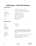
Страница 24: ...ly loaded 44 lbs Machine control Inputs 5 to ground Outputs Dry contact relays Functionality User definable Audio I O Number of I O cards Up to 8 either analog or digital Each card has 8 inputs and ou...

Страница 25: ...igital Audio Digital input format AES EBU and S PDIF selectable by channel Digital sampling rates 20 bit sample rate converters provided on all inputs Autodetect from 24kHz to 56kHz Input precision AE...

Страница 26: ...26 Appendix...

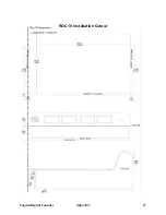
Страница 27: ...Logitek Digital Consoles Appendix 27 ROC 10 Installation Cutout...

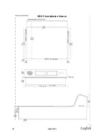
Страница 28: ...28 Appendix ROC 5 Installation Cutout...

Страница 29: ...rer in effect at the time of shipment of this order and Seller s obligation under this warranty shall be limited to such adjustment as Seller may obtain from the original manufacturer This limited war...

Отзывы: