background image


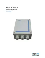
RTCU AX9i eco 

Technical Manual 

Version 1.01 


Содержание RTCU AX9i eco

Страница 1: ...RTCU AX9i eco Technical Manual Version 1 01...

Страница 2: ...rd as well as an external GSM antenna The RTCU AX9i eco is based on the X32 Execution Architecture offering high performance and a large memory capacity for both program and data meeting the requireme...

Страница 3: ...or implementation of Interactive Voice Response applications Large data flash logger memory with a capacity of 4 5 MB Internal 4 MB FAT32 flash drive 1 x RS232 channel 2 x analog inputs with 0 10 volt...

Страница 4: ...X9i eco Technical Manual V1 01 Logic IO ApS Ph 45 7625 0210 Holmboes All 14 Fax 45 7625 0211 8700 Horsens Page 4 of 30 Email support logicio com Denmark www logicio com THIS PAGE IS INTENTIONALLY LEFT...

Страница 5: ...se 14 Digital inputs S0 inputs wakeup ignition input 15 Analog input 17 USB programming port 18 RS232 communication ports EIA TIA 232 and V 28 V 24 compatible 18 RS232 port 1 18 1 Wire bus 19 LED Indi...

Страница 6: ...6 of 30 Email support logicio com Denmark www logicio com Graphical view On the front of the RTCU AX9i eco are four user controlled LED s and three system LED s for simple information and status The...

Страница 7: ...delivered with three PG11 glands and additional two PG9 blind plugs that can be replaced with PG9 glands if additional cable entry capacity should be required The stacked terminals contain connections...

Страница 8: ...3B Contact set for relay output 3 R4A R4B Contact set for relay output 4 N C Not connected PE Protective Earth terminal for AC supply DCIN DC power supply positive connection XGND DC power ground nega...

Страница 9: ...le SER1_RXD Receive data for serial port 1 RS232 compatible DEV_DET Reserved for accessories SGND Signal ground 1Wire 1 Wire bus for ID Button Temperature sensor 1Wire LED 1 Wire ID Button LED output...

Страница 10: ...in power down mode There are five different ground labels External Ground XGND Signal Ground SGND Digital Ground GND Analog Ground AGND and AC power ground PE The signal digital and analog grounds are...

Страница 11: ...pplied to the DCIN pin and ground is connected to the XGND pin The DC supply of the RTCU AX9i eco is protected against wrong polarity If a system ground are connected to either SGND or AGND a wrong po...

Страница 12: ...minals Terminal Name Description N N 85 265VAC 50 60Hz Null input internally connected P P 85 265VAC 50 60Hz Phase input internally connected PE Protective Earth connector Please Note The two pairs of...

Страница 13: ...it This must be taken in consideration when the AX9 series are supplied with AC supply When the AX9 is supplied with DC voltage this potential difference issue may not be observed as the DC power supp...

Страница 14: ...e relay outputs and therefore a source must always be connected to one of the relay terminals for the output to work If power is removed or a power fail occurs on the RTCU AX9i eco will switch to norm...

Страница 15: ...on input As default the digital inputs are configured as normal inputs For placement and configuration of the hardware jumpers inside the unit please refer to the configuration guide in Appendix A S0...

Страница 16: ...al level applied to this input must be greater than 2 ms to be valid The power management allows for the possibility of configuring a wakeup on one or more digital inputs with individually configured...

Страница 17: ...that deviations may occur as the system is very noise sensitive Avoid long unshielded wires and high current fast changing signals routed parallel to the analog signals Analog input terminals Terminal...

Страница 18: ...the unit and the PC RS232 communication ports EIA TIA 232 and V 28 V 24 compatible One general purpose RS232 ports available on the RTCU AX9i eco unit The serial input is compliant with the EIA TIA 23...

Страница 19: ...n regarding modular 1 wire concept please refer to the document Modular 1 Wire Concept Technical Manual on the Logic IO webpage 1 Wire terminals Name Description 1Wire 1 Wire bus 1Wire LED 1 Wire ID B...

Страница 20: ...he unit is executing the application program 1 5s On 0 5s Off green2 The unit is executing the application program while charging the internal back up battery Fast blinking red2 A runtime error has be...

Страница 21: ...e inside of the unit see drawing below or graphical view It s necessary to use a small object for example the tip of a pencil By activating the switch shortly the RTCU unit will do a complete reset as...

Страница 22: ...the battery ready for the next power fail A maintenance charge will start every 20 days after the last charge This is to compensate for the battery self discharge etc By default the battery cannot be...

Страница 23: ...ce and GPRS suspended CSD Datacall GSM Antenna The RTCU AX9i eco offers support for both an on board internal GSM antenna and a user supplied external antenna connected to the SMA female connector at...

Страница 24: ...he antenna is not in close proximity of metallic parts or anything else that can influence the efficiency of the GSM antenna SIM Card The RTCU AX9i eco unit contains a standard SIM card reader which i...

Страница 25: ...ve 65 50 20 mA Unit active with GSM on 80 60 25 mA GSM idle 67dBm Unit active RF sending 65 55 20 mA Unit active while charging 870 530 290 mA Unit in power down 1 3 0 8 0 4 mA Restart on DIN5 RTC Uni...

Страница 26: ...is powered from an external AC the power consumptions will be as follows Maximum power consumption 220VAC Unit active 8 VA Unit active with GSM on 8 5 VA GSM idle 67dBm Unit active RF sending 8 3 VA U...

Страница 27: ...A brief overview over the jumper settings can be found on the following table Feature Jumper State Default state JPAI1 Installed Not installed AI1 current measurement AI1 voltage measurement default...

Страница 28: ...th a jumper installed on the relevant analog input it will measure current between 0 20mA JPDI1 JPDI2 JPDI3 and JPDI4 These select either normal or Class A S0 input for DIN1 4 With the relevant jumper...

Страница 29: ...he SIM card Open the hinged lid of the SIM card reader orientate the card as showed below and insert it into the lid of the card reader Close the lid and slide the metal locking mechanism to the locke...

Страница 30: ...M on chip User Interaction 3 x bi colour LED Yellow status LED DIP switches Reset recovery switch Antenna selection dip switch Configuration jumpers USB B for service port Power Management 5 execution...

Отзывы: