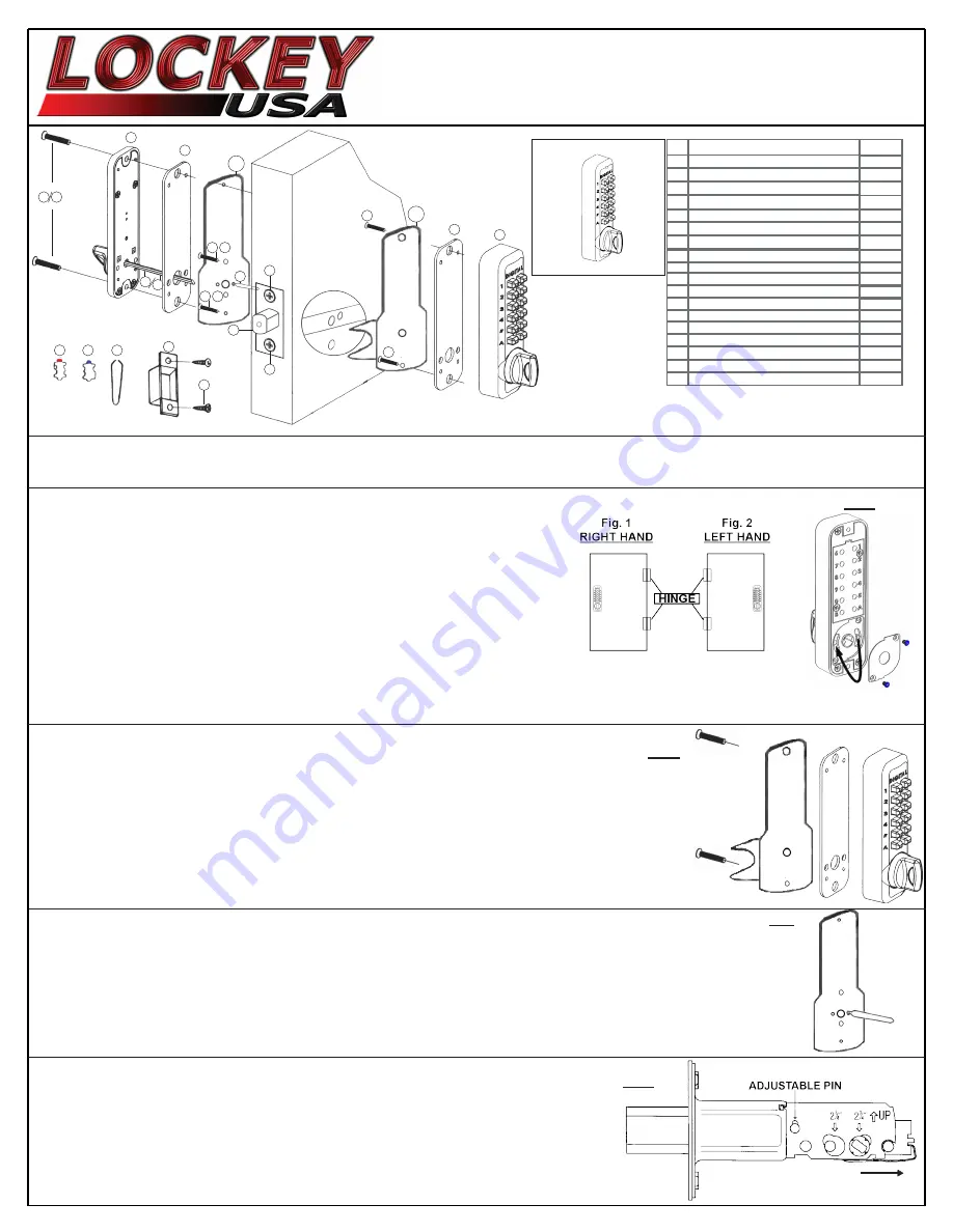
Digital M210EZ Deadbolt
Installation Instructions
M210EZDC
M210EZ
|
No.
Part Name
M210EZ
2
1
3
4
5
Outside Body
Inside Body
Rubber Trim Plate
Mortised Strike
Spindle 40-55mm.
Spindle 30-45mm.
Machine Screw M4 x 12mm
Machine Screw M4 x 25mm (DC)
Wood Screw M4
Extra Code Tumblers (Red)
Extra Non-Code Tumblers (Blue)
Adjustable Deadbolt 2 3/8” - 2 3/4”
Tweezers
Brass Support Pin
6
7
8
9
10
11
12
13
14
1
1
1
2
1
1
2
2
4
1
2
1
1
1
EZ Mounting Plates (A
&
B)
15
2
Machine Screw M4 x 35mm
16
2
Machine Screw M4 x 17mm
17
2
Machine Screw M5 x 1/2”
18
2
Step 1: Change User Code/Combination (OPTIONAL)
To change user code/combination, see instructions on reverse side.
Step 2: Identify Door Handing
(The M210EZ is pre-handed for right-hand doors)
Right-Hand Doors – From exterior of door, hinges are on right-side (Fig. 1).
Left-Hand Doors – From exterior of door, hinges are on left-side (Fig. 2).
To change handing for left-hand doors, use a #1 phillips screwdriver to remove
two blue screws and cover plate from Outside Body (Fig. 3).
Move the handing pin from the right side of the Outside Body to the hole on the left side.
Replace plate and screws.
*M210EZDC – Inside Body must be handed opposite from Outside Body.
Step 3: Place Outside Body on EZ Plate A
Place Rubber Trim Plate (#3) on EZ Plate A (#15).
Place the Outside Body (#1) on EZ Plate A and screw into place with two (2) M5 x 1/2” screws (#18).
Step 4: Install Brass Support Pin (Fig. 5)
Install Brass Support Pin (#14) into EZ Plate B (#15) on either side.
1
2
4
5
6
7 8
9
10
11
12
13
14
3
3
Fig. 3
INSTALLATION INSTRUCTIONS:
Inside Body M210EZDC:
DC= Double Combination
Continued on Reverse Side
Fig. 4
Fig. 5
Step 5: Adjust Deadbolt (if necessary) & Install
Adjustable Deadbolt (#12) is preset to 2 3/8” backset.
To adjust, lift pin and slide to 2 3/4” (Fig. 6).
With arrow pointed UP, insert Deadbolt and secure with two (2) Wood Screws (#9).
Fig. 6
LIFT
SLIDE
15A
15B
16 17
16 17
18
18
9
9


