Configuration and Settings
75
Interfaces
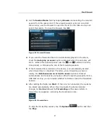
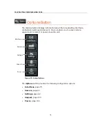
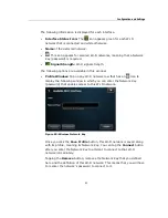
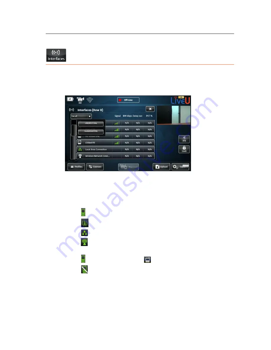
The Interfaces button enables you to view and configure the interfaces
(modem connections) of the LU. It displays the Interface Table, which shows a
list of all of the interfaces to which the LU unit is able to connect, as shown
below:
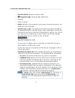
Figure 53: Configuration – Interface Table
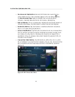
The following information is displayed for each interface. A more detailed
description is provided for some of these fields on page 78.
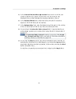
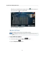
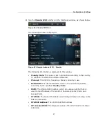
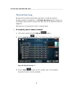
•
Interface Status Icon:
Represents a cellular network.
Represents cellular interfaces of the Xtender.
Represents a Local Area Network (LAN).
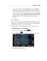
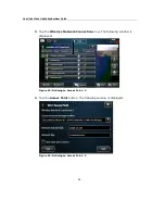
Represents Wi-Fi networks and external modems, as described in
the Defining a Wi-Fi Interface section on page 79.
Green means Connected.
White means Not Connected.
Strike-through means Manually Disabled by the user.
Instructions for manually disabling an interface are provided below.
Содержание LU60
Страница 1: ...LiveU Live Video Uplink System User Guide LU60 and LU70 Version 6 3 Part Number DOC00032...
Страница 12: ...LiveU Live Video Uplink System User Guide 12 Blank page for double sided printing...
Страница 18: ...LiveU Live Video Uplink System User Guide 18 Blank page for double sided printing...
Страница 46: ...LiveU Live Video Uplink System User Guide 46 Blank page for double sided printing...
Страница 62: ...LiveU Live Video Uplink System User Guide 62 Blank page for double sided printing...
Страница 72: ...LiveU Live Video Uplink System User Guide 72 Blank page for double sided printing...
Страница 111: ...LU Remote Control 111 3 Click the Login button The following window is displayed Figure 91 Remote Control Main Window 1...
Страница 124: ...LiveU Live Video Uplink System User Guide 124 Blank page for double sided printing...
Страница 132: ...LiveU Live Video Uplink System User Guide 132 Blank page for double sided printing...
Страница 138: ...LiveU Live Video Uplink System User Guide 138 Blank page for double sided printing...

