8-12
Structure Function Principle
January 24, 2017
Power System
CLG835H
If the diesel engine fails to start in three
consecutive trials, switch off the electric lock, and
implement the second starting round after 30
minutes. Inspect the battery and start circuit, if
necessary, to see whether there are failures in
the way of starting.
A majority of the start difficulties happen
outdoors in the cold winter, where the ambient
temperature may be even lower than 5°C. If
possible, try to start the diesel engine indoors
instead, or improve the start with auxiliary
heating.
For the disassembly of other components of the
machine induced by the electric lock removal or
installation, please refer to the corresponding
tool lists which are excluded from the section
hereof.
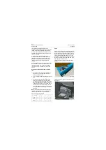
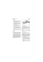
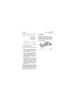
Procedures of failure detection for electric
lock
1. Unplug the connectors connected with the
electric lock, to separate the electric lock
from the machine circuit.
2. Turn the digital multimeter to 200
Ω
of
Ω
posi-
tion.
3. According to the electric lock gear logical
table, pins corresponding to "
●
" marked in
each gear should be connected, and the dis-
play value of multimeter should be "0" when
measuring; pins between "
●
" marked and "
●
"
unmarked should be disconnected, and the
value of multimeter should be "1" when mea-
suring. Otherwise, it can be judged as electric
lock fault.
Note:
"0" indicates the resistance between the
two pins is measured as zero; "1" indicates the
resistance between the two pins is infinite.
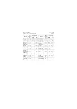
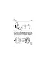
Fuse
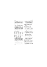
Fuse acts as protecting terminal equipment dur-
ing short circuit or overcurrent. Different series of
fuses are applied in the power system, such as
plug-in fuse and bolt fuse. The specifications of
plug-in fuse diversified from 20A to 15A, 10A,
7.5A and 5A, for the branch circuits. The specifi-
cations of bolt fuse ranges from 30A, 50A, 60A,
80A, 150A, for the main circuit.
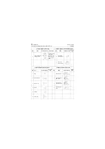
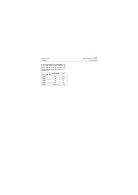
Electric lock gear logical table
Gears
Pin
1
2
3
4
5
6
OFF
●
●
IGN
●
●
●
●
START
●
●
●
●
●
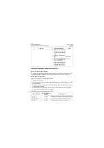
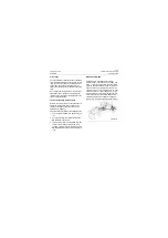
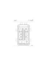
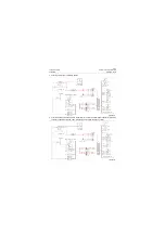
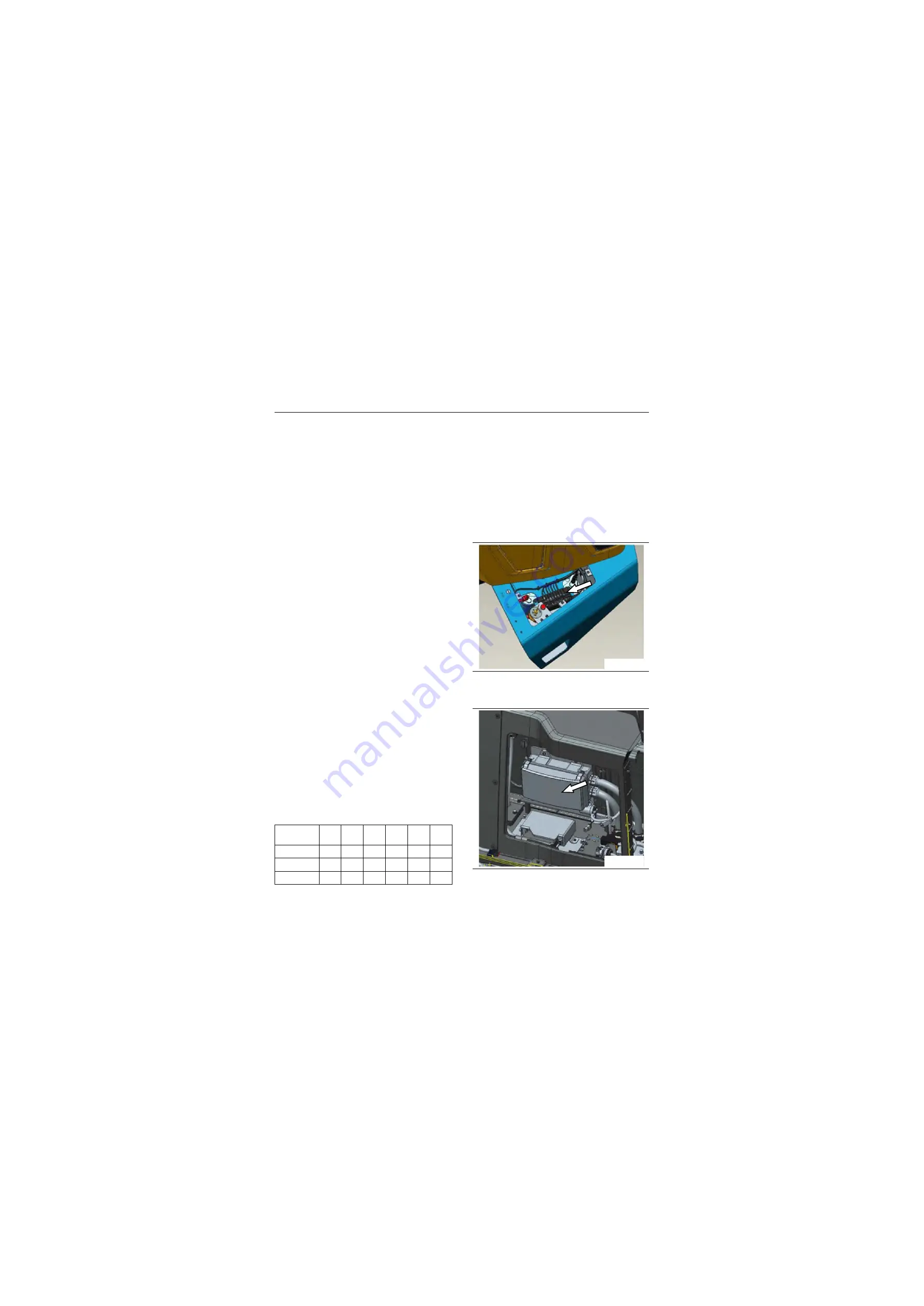
Location diagram of complete bolt type fusing
machine
Location diagram of complete inserting disk fus-
ing machine
P18E00007
P18E00008
Содержание CLG835H
Страница 2: ......
Страница 4: ...Contents January 24 2017 CLG835H...
Страница 6: ...1 2 General Information January 24 2017 CLG835H...
Страница 38: ...1 34 Machine Inspection Table January 24 2017 CLG835H...
Страница 154: ...2 116 Fault Diagnosis and Troubleshooting January 24 2017 Common fault code and troubleshooting CLG835H...
Страница 156: ...3 2 Power Train System January 24 2017 CLG835H...
Страница 214: ...3 2 Power Train System January 24 2017 CLG835H...
Страница 272: ...3 60 Testing and adjustment January 24 2017 Power Train Test CLG835H...
Страница 276: ...4 4 Hydraulic System January 24 2017 CLG835H...
Страница 296: ...4 24 Structure Function Principle January 24 2017 Work hydraulic system CLG835H Exploded view of control valve P18H00016...
Страница 297: ...4 25 January 24 2017 Structure Function Principle CLG835H Work hydraulic system Exploded view of control valve P18H00017...
Страница 308: ...4 36 Structure Function Principle January 24 2017 Work hydraulic system CLG835H Outline diagram of pilot valve P18H00027...
Страница 506: ...4 234 Fault Diagnosis and Troubleshooting January 24 2017 Common troubleshooting for brake system CLG835H...
Страница 552: ...6 2 Driver s Cab System January 24 2017 CLG835H...
Страница 606: ...6 56 Removal and Installation January 24 2017 Removal and installation of the engine hood torque mechanism CLG835H...
Страница 608: ...7 2 Structure January 24 2017 CLG835H...
Страница 662: ...8 4 Electrical System January 24 2017 CLG835H...
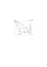
Страница 677: ...8 19 January 24 2017 Structure Function Principle CLG835H Power System P18E00014...
Страница 737: ...8 79 January 24 2017 Structure Function Principle CLG835H Audio system Audio system Audio system principle P18E00138...
Страница 756: ...9 2 Appendix January 24 2017 CLG835H...
Страница 757: ...9 3 January 24 2017 Schematic Diagram of Hydraulic System CLG835H Schematic Diagram of Hydraulic System...
Страница 758: ...9 4 January 24 2017 Schematic Diagram of Brake System CLG835H Schematic Diagram of Brake System...

