6-41
January 24, 2017
Removal and Installation
CLG835H
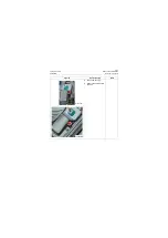
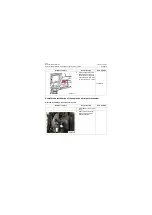
Installation of the left door lock in cab
Installation of the left door lock in cab
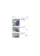
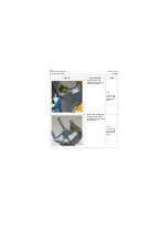
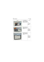
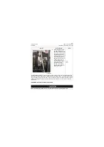
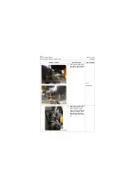
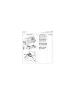
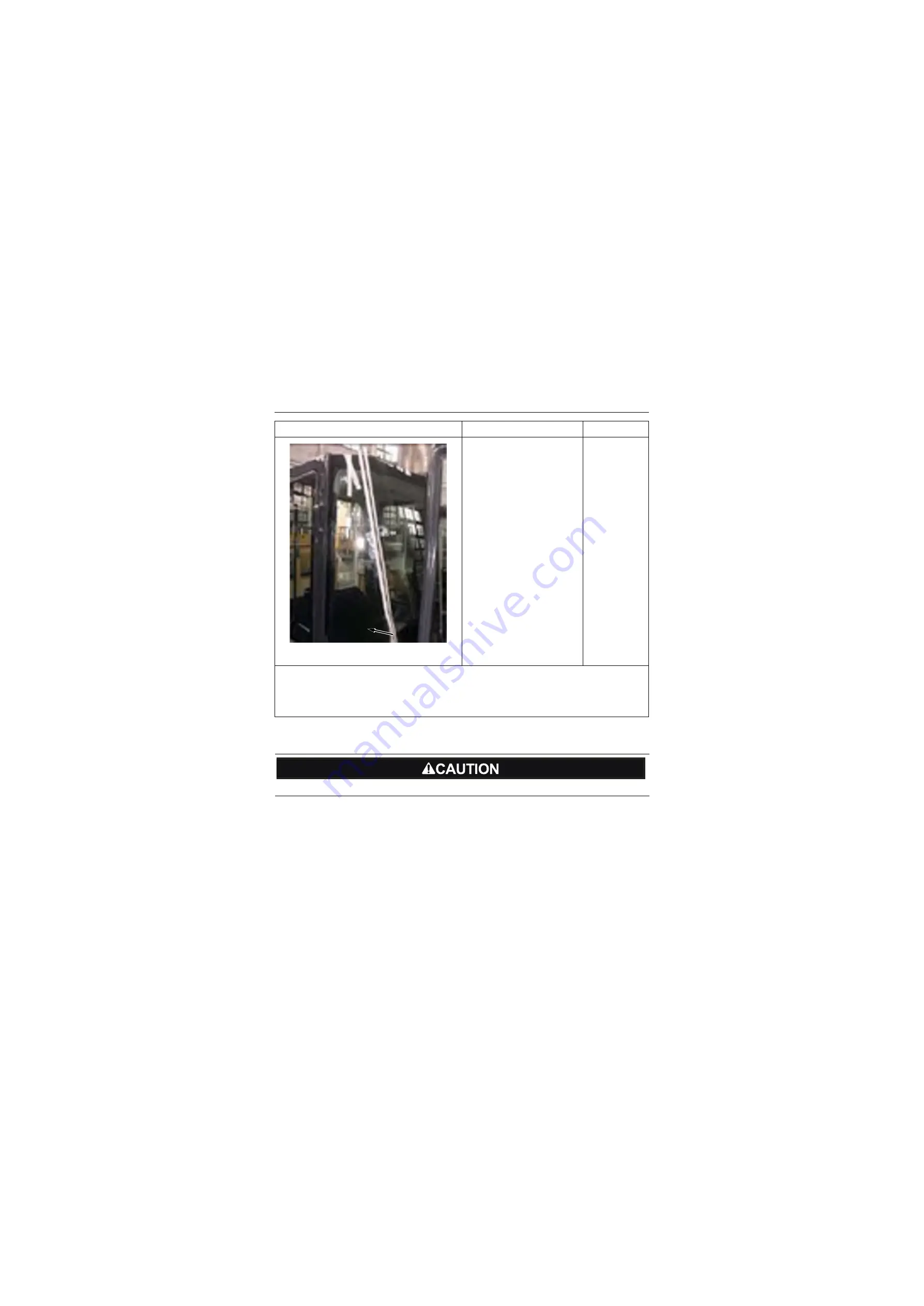
6. Glass joint filler: bond the
color separation paper on
both sides of adjacent glass
edge, about 5mm away from
the glass edge, and keep
the spacing formed by color
separation papers on both
sides consistent from up to
down; Meanwhile, seal the
inside of glass joint with
color separation paper to
avoid rugged adhesive on
the back when filling
adhesive. After applying
adhesive, flatten with self-
made rubber plate.
Tool:
Seal
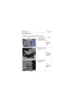
Technical requirements:
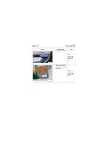
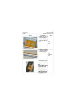
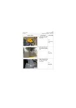
The speed of applying adhesive shall be even and the triangular adhesive
bead shall be uniform without lumps or breakpoints. Insertion depth is 2mm. The rubber blocks shall not
be placed within the scope of 10cm from corner point. The block shall not separate the adhesive bead.
Flatten excessive glue of sheet metal side not receiving filler treatment, and no excessive adhesive
shall remain.
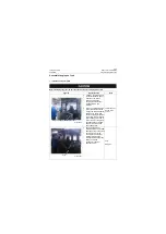
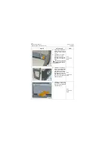
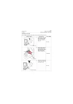
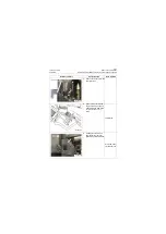
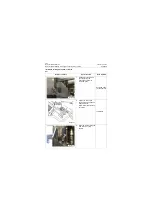
Before installing the left door lock, be sure that the machine is in parking brake state.
Figures
Operation step
Tools
P18C00084
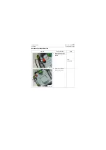
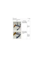
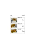
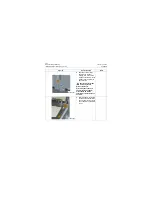
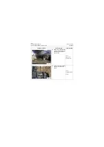
Glass gap filling sealant: One
line each on left and right for
both front and rear glasses
Содержание CLG835H
Страница 2: ......
Страница 4: ...Contents January 24 2017 CLG835H...
Страница 6: ...1 2 General Information January 24 2017 CLG835H...
Страница 38: ...1 34 Machine Inspection Table January 24 2017 CLG835H...
Страница 154: ...2 116 Fault Diagnosis and Troubleshooting January 24 2017 Common fault code and troubleshooting CLG835H...
Страница 156: ...3 2 Power Train System January 24 2017 CLG835H...
Страница 214: ...3 2 Power Train System January 24 2017 CLG835H...
Страница 272: ...3 60 Testing and adjustment January 24 2017 Power Train Test CLG835H...
Страница 276: ...4 4 Hydraulic System January 24 2017 CLG835H...
Страница 296: ...4 24 Structure Function Principle January 24 2017 Work hydraulic system CLG835H Exploded view of control valve P18H00016...
Страница 297: ...4 25 January 24 2017 Structure Function Principle CLG835H Work hydraulic system Exploded view of control valve P18H00017...
Страница 308: ...4 36 Structure Function Principle January 24 2017 Work hydraulic system CLG835H Outline diagram of pilot valve P18H00027...
Страница 506: ...4 234 Fault Diagnosis and Troubleshooting January 24 2017 Common troubleshooting for brake system CLG835H...
Страница 552: ...6 2 Driver s Cab System January 24 2017 CLG835H...
Страница 606: ...6 56 Removal and Installation January 24 2017 Removal and installation of the engine hood torque mechanism CLG835H...
Страница 608: ...7 2 Structure January 24 2017 CLG835H...
Страница 662: ...8 4 Electrical System January 24 2017 CLG835H...
Страница 677: ...8 19 January 24 2017 Structure Function Principle CLG835H Power System P18E00014...
Страница 737: ...8 79 January 24 2017 Structure Function Principle CLG835H Audio system Audio system Audio system principle P18E00138...
Страница 756: ...9 2 Appendix January 24 2017 CLG835H...
Страница 757: ...9 3 January 24 2017 Schematic Diagram of Hydraulic System CLG835H Schematic Diagram of Hydraulic System...
Страница 758: ...9 4 January 24 2017 Schematic Diagram of Brake System CLG835H Schematic Diagram of Brake System...

