background image

5-41

January 24, 2017

System Maintenance

CLG835H

A/C system regular maintenance

A/C refrigerant filling method

Because air conditioning system is not an absolutely airtight system, the problem of deficient refrigerant 
may occur after it is used for a period of time. At the moment, if refrigerant in the system is confirmed not 
to completely lose, start the operation of refilling refrigerant starting from step X of the instructions.

Even though there is only little water in air conditioning system, water vapor at low temperature 
part may be frozen to cause refrigerant circulation blockage or compressor valve corrosion, etc. 
Therefore, when refrigerant is refilled after parts are replaced or air conditioning system is rein-
stalled in complete machine, strictly vacuum pumping, maintain pressure to check leakages and 
continue to refill refrigerant after system airtightness is confirmed to be good.

Figures

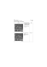
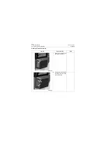
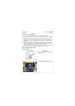
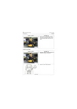
Operation step

Tools

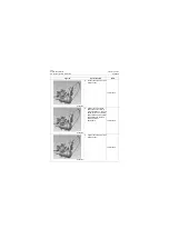
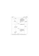
1. Connect manifold gauge 

and A/C filler according to 
the sequence specified in 
Release (Recover) Refriger-
ant in Air Conditioning Sys-
tem, and make sure there is 
no refrigerant in the system.

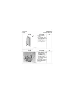
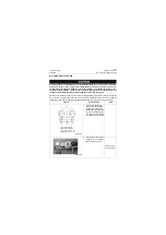
2. Connect the hose connect-

ing port A on the manifold 
gauge to vacuum pump.

Vacuum pump, 
manifold meter

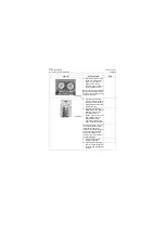
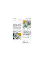
1.Low pressure gauge
2.High pressure gauge

3.Low pressure valve

δ

LO

ε

4.High pressure valve

δ

HI

ε

P18A00043

P18A00044

Содержание CLG835H

Страница 1: ...201701001 CLG835H WHEEL LOADER SERVICE MANUAL Applicable type and model CLG835H PERKINS Engine 1204F E44AT LIUGONG Wet Axle ZF 4WG158 Gearbox...

Страница 2: ......

Страница 3: ...7 Contents CLG835H Contents General Information 1 1 Power System 2 1 Power Train System 3 1 Hydraulic System 4 1 Air Conditioning System 5 1 Driver s Cab System 6 1 Structure 7 1 Electrical System 8 1...

Страница 4: ...Contents January 24 2017 CLG835H...

Страница 5: ...cation of Complete Machine and System 1 5 Engine Identification 1 6 Cable Code Identification 1 8 Coating Materials 1 10 Weight Table 1 12 Unit conversion table 1 14 Standard Torque Table 1 15 Oils us...

Страница 6: ...1 2 General Information January 24 2017 CLG835H...

Страница 7: ...rmation needed for diagnosis analysis testing and repair Fundamental service information is available from other sources covering basic theory of oper ation fundamentals of troubleshooting general mai...

Страница 8: ...ing explaining the hazard can be either written or pictorially presented Operations that may cause product damage are identified by NOTICE labels on the product and in this publication LiuGong cannot...

Страница 9: ...into which they are sold Different sup porting manuals exist for different machine con figurations When necessary product serial numbers and engine model numbers are listed on the front covers of load...

Страница 10: ...numbers LIST NO and SERIAL NO shown on this plate Engine Emission Level Identification EMISSION CONTROL INFORMATION In the U S this engine is solely for export and is therefore exempt under 40 CFR 106...

Страница 11: ...1 7 January 24 2017 Engine Identification CLG835H Figure 3 Engine Serial Number Plate Location Figure 4 Engine Serial Number Plate P11000003 P11000004...

Страница 12: ...Wire name Description Heat resis tance 1 QVR Low voltage wire for road vehicles 70 C 158 F heat resisting cop per core PVC insulated 70 C 158 F 2 AVSS Thin wall insulated low voltage wire for vehicle...

Страница 13: ...04 F 50 C 122 F 60 C 140 F 70 C 158 F Allowable current voltage drop A mV m A mV m A mV m A mV m A mV m Nominal sectional area mm2 0 85 18 463 16 412 14 360 11 283 8 206 1 25 23 407 21 372 18 319 14 2...

Страница 14: ...ium sealing oil air vapor water pipeline cone taper thread Purposes used for water temperature sensor and oil pressure sensor Cleaning agent for electro mechanical equipment HD 10 Used for cleaning oi...

Страница 15: ...adhesive tape and compact then tear off the tape Approval standard No the whole piece of grid film drops Little film drop around the scrib ing lines can be allow able 5 Color dif ference Meet color d...

Страница 16: ...kg 463 lb Left rear fender 27 kg 60 lb Right rear fender 30 kg 66 lb Air conditioner 100 kg 221 lb Steering pump 34 kg 75 lb Control valve 45 kg 99 lb Fan drive motor 12 kg 26 lb Hydraulic oil tank 13...

Страница 17: ...gure Parameters Metric unit British unit Multiple Length mm In 0 03937 mm ft 0 003281 Capacity L US gal 0 2642 L US qt 1 057 m Yd3 1 308 Weight kg lb 2 205 Intensity N kgf 0 10197 N lbf 0 2248 Torque...

Страница 18: ...N m 89 7 lbf ft M14 195 15 N m 144 11 lbf ft M16 305 25 N m 225 18 lbf ft M18 415 35 N m 306 26 lbf ft M20 600 50 N m 443 37 lbf ft M22 800 70 N m 590 52 lbf ft M24 1020 100 N m 752 74 lbf ft M27 1500...

Страница 19: ...116 5 11 8 0 5 M36 2 25 137 6 14 0 0 6 M45 2 31 5 226 11 23 1 1 1 M52 2 38 347 16 35 4 1 6 Heavy type M14 1 5 5 26 2 2 7 0 2 M16 1 5 6 3 42 2 4 3 0 2 M18 1 5 6 3 53 2 5 4 0 2 M20 1 5 8 63 3 6 4 0 3 M...

Страница 20: ...12 136 6 12 8 0 6 M16 310 15 31 6 1 5 M20 577 27 58 9 2 8 Material of fasten ings Carbon steel alloy steel Aluminum product Thread size Tightening torque Tightening torque N m kgf m N m kgf m G1 8 8 7...

Страница 21: ...ystem steering hydraulic system 25 40 C 13 104 F HV 46 low temperature anti wear hydraulic oil Torque converter oil 10 C 14 F SAE 15W 40 Mobil Delvac 1300 40L 11 US gal Torque converter and power shif...

Страница 22: ...loud Point C The cloud point must not exceed the lowest expected ambient temperature ISO 3015 Copper Strip Corrosion _ No 3 maximum ISO 2160 Density at 15 C 59 F Kg m3 801 minimum and 876 maximum ISO...

Страница 23: ...0 First 100 Hours Change Engine Oil and Filters 100 Replace Fuel Filters 100 Change Hydraulic Filter 100 Change Transmission Oil and Filter 100 Change Oil in Axles 100 Every 100 Hours Grease Front Dri...

Страница 24: ...Front Rear Axle Oil 1000 Replace Cab Fresh Air Filter 1000 Replace AC Return Air Filter 1000 Change Transmission Oil and Filter 100 1000 Check Accumulator Nitrogen Press 500 1000 Clean Fuel Tank 100 1...

Страница 25: ...s not suitable for the flammable explosive dusty and air poisonous environments Requirements of Work Environments 1 Altitude 3000 m 2 Environmental temperature 15 C 40 C The cold starting Aid device i...

Страница 26: ...ront combination lights 5 Front work lights 6 Cab 7 Rear fender 8 Counterweight 9 Rear wheel 10 Hydraulic oil tank 11 Front frame 12 Front fender 13 Boom cylinder 14 Front wheel 15 Boom 16 Engine hood...

Страница 27: ...that deviate from these criteria e g on soft or uneven ground on a slope or when subject to slide loads these conditions shall be taken into account by the operator The following table lists the speci...

Страница 28: ...eight fully raised mm In 2700 106 2800 110 3 C Dumping reach fully raised mm In 1150 45 1076 42 4 D Max digging depth mm In 100 4 80 3 5 E Min ground clearance at articulation joint mm In 325 13 325 1...

Страница 29: ...Alternator V A 24V 70A Power train system 1 Torque converter Type Single turbine three members 2 Transmission Manufacturer ZF 3 Model 4WG158A 4 Type Fixed shaft type power shift 5 Number of gears Fou...

Страница 30: ...steering system pressure Mpa psi 16 2320 9 Secondary steering system flow L min US gpm 22 25l min 5 8 6 6gpm 52bar Brake hydraulic system 1 Service brake Type Full hydraulic wet type brake 2 Brake pum...

Страница 31: ...g are provided by LiuGong standard 4 Transmission oil L US gal 40 10 57 5 Drive axle oil L US gal 34 8 98 6 Hydraulic oil L US gal 120 31 7 7 AdBlue L US gal 19 5 02 Other specifications 1 Cooling pum...

Страница 32: ...d fluid MAX and MIN marks Then place the shift lever at four gear and depress the brake then the accelerator to run the transmis sion for 5 8min resulting in the transmission fluid temperature reachin...

Страница 33: ...ket 6 Pilot shutoff function the pilot shutoff lever is at OFF position operate the pilot lever and the work implement shall not act the pilot shutoff lever is not installed reversely and has no inter...

Страница 34: ...hift up to F3 7 Keep the opening of throttle and continuously increase the vehicle speed and operate the shift lever and place it at F4 and when the speed reaches a certain value the gear shall automa...

Страница 35: ...ehicle shall stay for 5 seconds and remain stationary 28 Pressure maintaining of hydraulic system extend and retract all oil cylinders to the maximum with control lever remained open at each end of tr...

Страница 36: ...return pipe joints to the boom bucket tilting control valve pilot hose joint on the control valve visually check that there is no interference between oil inlet and return pipe of control valve pilot...

Страница 37: ...emperature area 22 Visual check A C pipe runs smoothly and is not interfered with other parts diesel engine high temperature area and the exposed A C aluminium pipe is not interfered with other parts...

Страница 38: ...1 34 Machine Inspection Table January 24 2017 CLG835H...

Страница 39: ...y 2 31 DEF tank 2 33 DEF pump 2 36 Cooling system 2 38 Overview 2 38 Radiator group 2 43 Fan 2 45 Refilling and replacement of coolant 2 45 Fuel System 2 46 Fuel Tank Assembly 2 46 Fuel Lines 2 47 Rem...

Страница 40: ...mbly and assembly of radiator 2 100 Removal and installation of fan 2 106 Removal and installation of fuel tank 2 111 Removal and installation of fuel radiator 2 115 Fault Diagnosis and Troubleshootin...

Страница 41: ...draining liquid Do not use the food or drink containers because they may be drunk by others by mistake Preventing Burns After running for some time parts of the machine will be hot such as engine DPF...

Страница 42: ...with oil soaked into protective container and set it at a safe place Do not perform welding or flame cutting onto the pipe containing flammable liquid Before welding or cutting it shall be shall be cl...

Страница 43: ...des engine system radiator system and fuel tank assembly Among them the engine mounting consists of engine and the radiator mounting consists of cooler com ponents Module structure figure of power sys...

Страница 44: ...2 6 Basic Information January 24 2017 Overview components and position CLG835H Position figure of power system in the machine 1 Engine system 2 Cooling system 3 Fuel tank assembly P18P00007 1 2 3...

Страница 45: ...ic Information CLG835H Overview components and position Components of power system 1 Diesel particle filter DOC 2 Diesel engine 3 DEF pump 4 DEF tank 5 Radiator mounting assembly 6 Oil water separator...

Страница 46: ...ry 24 2017 Overview components and position CLG835H Components of power system 7 Air filter 8 Fuel fine filter 9 Oil drain device 10 Solenoid water valve 11 Diesel particle filter SCR 12 Exhaust pipe...

Страница 47: ...to flywheel housing end Cooling system Fan Diameter of 880mm 34 6456In 12 pieces of blades air suction type Thermostat Opening temperature 82 C 179 6 F Fully open temperature 94 C 201 2 F Engine oil s...

Страница 48: ...sing etc during reassembly 4 If the removal and installation of other com ponents on the complete machine are con cerned in the removal and installation of each component tools are referred to the too...

Страница 49: ...environment through shock isolating action of shock absorber vibration of engine transferred to complete machine is reduced and riding comfort is improved Generally requirements for the engine assembl...

Страница 50: ...ne mounting and influence of road impact on engine is reduced Diesel engine Technical parameters Model Perkins 1204F E44TA Number of cylinder 4 Cylinder diameter 105 mm 0 344505ft Stroke 127 mm 0 4166...

Страница 51: ...gine 1204F E44TA 1 Front lifting eye 2 Crankcase breather 3 Secondary fuel filter 4 Primary fuel fitter 5 Electronic Control Module 6 Pnmiog trarferfuel pump 7 In line fuel fitier 8 Oil level gauge di...

Страница 52: ...2 14 Structure Function Principle January 24 2017 Engine system CLG835H 14 Air intake 15 Coolant outlet 16 Water pump 17 Coolant intake 18 Tensioner 19 Belt P18P00012 14 15 16 17 18 19...

Страница 53: ...21 Htgh pressure turtoocharger 22 Low pressure turbocharger 23 Alternator 24 Refrigerant compressor 25 Starter solenoid 26 Starting motor 27 Starter relay 28 Oil dram tap 29 Flywheel 30 Flywheel housi...

Страница 54: ...r systems Basic body of engine Engine body and cylinder head It is the frame of engine and composed of cylinder block crankshaft case and oil pan Engine body Diesel engine Engine body and cylinder hea...

Страница 55: ...ylinder and piston It is usually installed with nozzle air intake exhaust valve intake exhaust pipe and rocker arm shaft assembly Cylinder head P18P00016 Machine body and work compo nent which is comp...

Страница 56: ...of dome head flat head crown head Piston group It is composed of connecting rod connecting rod bolt and connecting rod bearing The connecting rod is used for con verting the reciprocating motion of p...

Страница 57: ...is composed of valve group and valve train and mainly used for controlling the intake exhaust process of engine and ensuring that the fresh air is filled into the cylinder timely and making the exhau...

Страница 58: ...m Valve group It is composed of camshaft tap pet push rod rocker arm timing gear Valve train P18P00022 1 Valve guide pipe 2 Valve 3 Valve spring 4 Valve seat ring 3 1 2 4 P18P00023 1 Bucket lever 2 Pu...

Страница 59: ...ngine operate under the proper temperature Thermostat It is built into the machine body to allow the cooling water flow over each component to be cooled Water channel P18P00024 P18P00025 P18P00025 Com...

Страница 60: ...supplying fuel to engine Fuel system It is used for filtering the larger particles of impurity and installed at the front of fuel inlet line fuel delivery pump Fuel coarse fil ter oil water separator...

Страница 61: ...that the battery can provide high enough voltage during the engine cranking Alternator It pushes the turbo to drive the vane rotating at high speed by using the high speed of exhaust to increase inta...

Страница 62: ...exhaust pipe Description of principle diagram and working principle The functions of the intake and exhaust assembly are 1 Supply clean and dry air with proper temperature for engine to burn so as to...

Страница 63: ...roper temperature and then enters engine block to burn Exhaust gas generated after combustion reaches turbocharger via exhaust manifold drives turbocharger to pressurize intake air and is then dis cha...

Страница 64: ...Function Principle January 24 2017 Intake and exhaust system CLG835H Exhaust path figure of engine 1 Turbocharger 2 Diesel oxidation catalyst DOC 3 Selective catalytic reducer SCR Hot gas Cold gas P1...

Страница 65: ...2 27 January 24 2017 Structure Function Principle CLG835H Intake and exhaust system Air filter Technical parameters P18P00035...

Страница 66: ...as shown in figure below Air filter blocked alert of this machine is the electronic induction type When the filter works for a period of time much dust is accumulated on filter element and air resista...

Страница 67: ...h the emission standard of Tier 4Final Euro Stage IV Terminology DOC Diesel Oxidation Catalyst SCR Selective Catalytic Reduction Diesel particle filter of the model adopts DOC SCR routine When exhaust...

Страница 68: ...nuary 24 2017 DEF pipeline assembly CLG835H DEF pipeline assembly Components and position DEF pipe line assembly includes DEF tank DEF pump DEF pipe line and water way 1 DEF tank 2 DEF pump 3 DEF pipe...

Страница 69: ...Particle Filter system in order to reduce nitride oxides content of exhaust DEF is pumped to DEF pump from DEF tank via outlet pipe and then transported to injector via pressure pipe Excess urea retu...

Страница 70: ...to prevent urea solution from freeze however when urea tem perature exceeds 5 C 41 F the solenoid water valve of water way closes to prevent urea solution from precipitation out because of being exces...

Страница 71: ...oolant enters into def tank to prevent DEF solution from freezing however when DEF temperature exceeds 5 C the solenoid water valve is closed to block coolant entering and prevent DEF solution from be...

Страница 72: ...it 1 DEF level and temp sensor assembly 2 DEF tank heating tube engine coolant flow internally 3 DEF suction filter on pick up 4 DEF outlet 5 Coolant inlet 6 Electrical connection flying lead 375mm lo...

Страница 73: ...CU 2 Mounting Tab 3 PEU Harness Connectror 4 Mounting Tab 5 DEF Outlet to injector 6 DEF inlet from Tank 7 Mounting Tab 8 Harness Restraint 9 Vent 10 Mounting Tab 11 Cap for serviceable filter on top...

Страница 74: ...2 36 Structure Function Principle January 24 2017 DEF pipeline assembly CLG835H 1 Protection shield 2 Strainer assembly 3 Housing P18P00045 1 2 3...

Страница 75: ...Principle CLG835H Cooling system Cooling system Overview Components and position The radiator system is composed of radiator mounting radiator pipe and oil drain device 1 Radiator mounting 2 Radiator...

Страница 76: ...is to radiate heat produced by each part or system into the air along with cooling air in order to ensure each part works properly in appropriate temperature range As shown below diesel engine cooling...

Страница 77: ...flows up to cool cylinder head and is collected by water outlet header pipe to reach thermostat When coolant temperature is lower than 84 C 183 2 F thermostat is closed and all coolant is bypassed to...

Страница 78: ...rises up sharply pressure is increased air flows into air air intercooler from left air pipe and passes across core of air air intercooler external cooling air flows by outside the core to bring away...

Страница 79: ...m of the vehicle arranged as the drawing below Hydraulic oil radiator Hydraulic oil radiator has the main function of radiating heat generated by hydraulic oil during the work ing of hydraulic system...

Страница 80: ...ator group P18P00051 Technical parameters Water radiator Core type Plate fin type Core size height width thickness 870mm X 454mm X 120mm 34 2519In X 17 87398In X 4 7244In Hydraulic oil radiator Core t...

Страница 81: ...system Part Structure The radiator assembly is composed of air air intercooler water radiator hydraulic oil radiator and torque converter oil radiator 1 Water radiator 2 Hydraulic oil radiator 3 Air...

Страница 82: ...o the con tainer and tighten water drain valve after draining coolant 6 Slowly open auxiliary tank cover wait until engine coolant temperature drops to be below 50 C 122 F slowly add coolant until coo...

Страница 83: ...835H Fuel System Fuel System Fuel Tank Assembly Technical parameters Part Structure and Principle Introduction The fuel tank assembly is mainly composed of fuel tank filler pipe breather pipe fuel tan...

Страница 84: ...le January 24 2017 Fuel System CLG835H Fuel Lines Overview components and position The fuel line is composed of fuel hose fuel filter and fuel radiator 1 Fuel radiator 2 Oil water separator 3 Fuel hos...

Страница 85: ...gh pressure fuel pump and filled into high pressure common rail Then the fuel in the common rail enters into injector while the spare fuel returns back to the outlet of high pressure fuel pump The inj...

Страница 86: ...l engine CLG835H Removal and Installation Removal and installation of diesel engine Removal Figures Contents Tools 1 Turn off the negative elec trode switch and hang on a No operating warning board P1...

Страница 87: ...removal steps of diesel particle filter and seal every port with plastic seal membrane as required 4 Drain the cooled water in the engine to oil collection dish for unified disposal 5 Remove electrica...

Страница 88: ...mbrane 8 Unscrew the intercooler pipe fixing clamp and bracket Unscrew the clamps at both ends of intercooler pipe unplug the pipe and seal every port with plastic seal membrane Tool Open end wrench 1...

Страница 89: ...ne unplug the water inlet pipe outlet pipe and seal every port with plastic seal mem brane Tool Open end wrench 8 Plastic sealing membrane 11 Unscrew the clamp at the connection of water inlet pipe an...

Страница 90: ...ket and tilt it to the radiator direction by an angle to avoid interfer ence when lifting the engine 13 Slowly operate traveling crane hang lifting eye on engine with hook on wire rope and tauten wire...

Страница 91: ...removal and installation requirements and steps of transmission torque converter assembly 15 Hold fixing nut of engine with an open end wrench and remove captive bolt of engine from under engine moun...

Страница 92: ...fting hook to pass hook through lifting hole at pulley side of engine and lift engine as slowly as possible It is recommended that lifting height is not more than 5 mm Traveling crane Wire rope with h...

Страница 93: ...ensure that engine is slowly and steadily lifted out of com plete machine and will not collide with other parts of complete machine 19 Loosen captive bolt of engine mounting support with an open end...

Страница 94: ...pport and pre tighten captive bolt with an open end wrench 2 Tighten mounting base cap tive bolt of engine with a torque wrench to torque of 120 50N m 12 5kgf m Tool Open end wrench 16 torque wrench 1...

Страница 95: ...ible to match the engine surface and gearbox torque converter assembly surface and align the holes 5 Install and tighten the bolts and hard washer of the torque converter housing the engine housing Ti...

Страница 96: ...spanner 7 Assemble shock absorber cap and engine mounting support together by passing engine fasteners such as captive bolt and nut through them Tool Open end wrench 16 8 Hold nut with an open end wre...

Страница 97: ...tion of diesel engine 11 Push the heat insulation bracket to installation posi tion and tighten the 4 anchor bolts Tool 12 Insert the water inlet pipe into hot water inlet of engine then clamp it with...

Страница 98: ...mp it with a clamp Insert the intake pipe into intake hose and clamp it with a clamp Tool Open end wrench 8 15 Insert the intercooler pipe into silicone hose on the engine and radiator and clamp it wi...

Страница 99: ...in Tool Open end wrench 19 17 Install the A C compressor A C pipe and warm air water pipe to the engine according to the installation require ments and steps of air con ditioning system 18 Install th...

Страница 100: ...Install the air filter according to the installation steps of air filter described 21 Install the engine hood according to installation steps of engine hood 22 Open the engine hood and fill the anti...

Страница 101: ...igures Contents Tools 1 Put out the harness connec tor on the air filter and seal every ports with plastic seal ing membrane as required Tool 2 Loosen the clamp connect ing air filter and intake pipe...

Страница 102: ...r fil ter mounting plate with wrench then remove the air filter with mounting plate Tool Open end wrench 13 4 Remove captive bolts of air filter with open end wrench and remove air filter Remove the b...

Страница 103: ...Tools 1 Fix the air filter on the mounting plate with bolts Tool Open end wrench 10 2 Install the air filter with the mounting plate on the heat insulation bracket Tool Open end wrench 13 3 Install th...

Страница 104: ...ess the indicator end face to reset it Tool 5 Check the inner of connec tors on the air filter and indi cator for water or sand If any clean them up Plug the harness connector on the two connectors To...

Страница 105: ...any visible damage do not install them 2 Take out the main filter ele ment along the direction of housing It can be taken out directly by hand and then take out the main filter ele ment by sequence 3...

Страница 106: ...e filter element is already firm and flat in the housing It needs no other tooling or tools in the assembly process 2 Insert the main filter ele ment Push downward the filter element at 5 angle until...

Страница 107: ...s 1 Turn off the negative elec trode switch and hang on a No operating warning board 2 Remove the mounting bolt of the exhaust pipe and take off the exhaust pipe Tool Open end wrench 13 3 Remove the e...

Страница 108: ...ipe joint and electrical connector on the DOC 5 Unplug the exhaust pipe and SCR electric connector Remove the U clamp and clamp take off the exhaust pipe Tool Open end wrench 11 6 Loose the clamp of D...

Страница 109: ...each port with plastic seal membrane Tool Open end wrench 18 Traveling crane Wire rope with hooks Plastic sealing membrane Figures Contents Tools P18P00106 Figures Contents Tools 1 Lift the diesel par...

Страница 110: ...amp and U clamp and insert the electric connector Tool Open end wrench 11 4 Connect the DEF pipe and insert the electric connector 5 Install the engine hood and top cover according to removal and inst...

Страница 111: ...Contents Tools 1 Stop the vehicle and turn off the negative electrode switch and hang on a No operating warning board when the urea pump stops operating 2 Open the engine hood and remove the protecti...

Страница 112: ...Seal every port with plastic sealing membrane as required Tool Straight screw driver Plastic sealing membrane 4 Remove the 4 captive bolts from the DEF bracket and take out the DEF tank from the count...

Страница 113: ...and tighten the strap bolt Tool Open end wrench 10 2 Put the DEF tank into install ing position from the coun terweight bottom and tighten the 4 captive bolts Tool 3 Insert the quick joint of urea pi...

Страница 114: ...ipe connected to solenoid water valve is inlet pipe which is con nected to the water inlet on the urea tank with arrow indicated Tool Straight screw driver 5 Insert the urea filler to the urea tank an...

Страница 115: ...of DEF tank Disassembly 7 Put on the fuel tank protec tion plate and tighten with bolts Tool Open end wrench 13 Figures Contents Tools P18P00124 P18P00124 Figures Contents Tools 1 Unscrew the retentio...

Страница 116: ...athead screw driver gently pry around where the head unit is con nected to the reservoir while simultaneously pulling on the top of the unit Continue until DEF mounting base is free from reservoir DO...

Страница 117: ...4 2017 Removal and Installation CLG835H Disassembly and assembly of DEF tank 3 Pull the DEF head unit out until the bottom of the header is at the bottom of the tank bore Figures Contents Tools P18P00...

Страница 118: ...the bottom of the header is posi tioned inside the tank bore When the bottom of the header is in the tank bore fold the filter downward towards the interior of the tank Continue to carefully remove t...

Страница 119: ...Bore seal O ring 2 Fold the Filter element in half towards the bottom of the Tri Function Sensor Tilt the header to an approxi mate 45 angle with respect to the top of the tank With the heel of the Tr...

Страница 120: ...mbly of DEF tank CLG835H 3 Position the DEF head unit in the desired orientation and press on the top of the blue mounting base until it is completely seated in the tank bore DO NOT press directly on...

Страница 121: ...ssembly and assembly of DEF tank 4 Position the retaining ring on Head unit and install the retention screws using the T25 Torxwrench Recom mended torque on screws is 20 30 in lbs 2 26 3 38 N m Tool T...

Страница 122: ...ures Contents Tools 1 Write 1 2 3 on the stickers respectively and stick them on the three DEF pipes from left to right Pull out the urea pipe harness connector from the urea pump Seal every port with...

Страница 123: ...Contents Tools 1 Fix the urea pump on the bracket and tighten it with bolts The recommended tightening torque is 15 2 22 8 N m Tool Wrench 13 2 Insert the three urea pipes to the urea pump by the ord...

Страница 124: ...f DEF pump CLG835H Disassembly and assembly of DEF pump Disassembly Figures Contents Tools 1 Unscrew the filter element cover by hand 2 Take out the filter element assembly upward and verti cally P18P...

Страница 125: ...cause urea leakage Check the thread of filter element cover for damage and if does replace it with a new one Check the thread of urea pump body If the thread is damaged replace the com plete urea pum...

Страница 126: ...EF pump housing with filter ele ment assembly tightening torque 14N M 124lbin and then tighten the protective cover Tool Open end wrench 27 2 Turn on the negative switch and start the engine check the...

Страница 127: ...egative elec trode switch and hang on a No operating warning board 2 Remove the engine hood and top cover according to removal and installation requirements and steps of engine hood 3 Unscrew the drai...

Страница 128: ...end wrench 36 Oil tank 5 Unscrew the torque con verter oil drain connector to drain the torque converter oil in the radiator Tool Open end wrench 36 Oil tank 6 Unscrew the clamp of inter cooler pipe u...

Страница 129: ...every port with plastic seal ing membrane Tool Open end wrench 8 Plastic sealing membrane 8 Remove the oil inlet return pipes of the torque converter oil radiator drain pipe joint unplug the temperat...

Страница 130: ...plastic seal membrane Tool Open end wrench Plastic sealing membrane 10 Remove the oil inlet return pipe connectors of the fuel radiator and seal each port with plastic seal membrane Tool Open end wre...

Страница 131: ...each port with plastic seal mem brane Tool Open end wrench Plastic sealing membrane 13 Slowly operate traveling crane hang lifting eyes with wire rope and tauten wire rope but not lift yet Tool Travel...

Страница 132: ...iator assembly slowly and put it on flat ground Tool Traveling crane Graph Contents Tools P18P00163 Graph Contents Tools 1 Uplift the traveling crane lift the radiator assembly to installing position...

Страница 133: ...of radiator 3 Loose the wire rope Tool 4 Install the oil inlet outlet return pipe connectors of cooling motor Tool Open end wrench 5 Install the condensing agent inlet outlet connectors of the A C ra...

Страница 134: ...tor CLG835H 6 Install the oil inlet outlet con nectors of fuel radiator Tool Open end wrench 7 Install the oil inlet return pipes of the hydraulic oil radiator drain pipe joint insert the temperature...

Страница 135: ...eturn pipes of the torque converter oil radiator drain pipe joint insert the temperature sen sor connector Tool Open end wrench 9 Insert the water inlet outlet pipes into the water radiator about 50mm...

Страница 136: ...a clamp Tool Open end wrench 12 11 Tighten the radiator water draining switch torque con verter oil draining switch and hydraulic oil draining switch Tool 12 Replenish the coolant hydraulic oil and to...

Страница 137: ...ly Graph Contents Tools 1 Unscrew the 4 fixing bolts on the upper connecting plate remove the bolts and con necting plate Tool Open end wrench 16 2 Unscrew 4 captive bolts do not remove of lower con n...

Страница 138: ...e notice that the direction of compressed air shall be inverse with that of air which passed through the radiator during normal operation of the machine 3 Push the radiator to right by the order 4321...

Страница 139: ...r con necting plate with bolts but not tighten the bolts so that left and right supports and lower connecting plate can rotate relatively and place the sponge on the lower backing plate 2 Put the shoc...

Страница 140: ...l Open end wrench 16 4 Install the upper plate and tighten the 4 captive bolts of the upper and lower con necting plates CAUTION The radiator assembly shall be held by someone or using corresponding s...

Страница 141: ...installation of fan Removal and installation of fan Removal Graph Contents Tools 1 Turn off the negative elec trode switch and hang on a No operating warning board 2 Open engine hood P18P00183 P18P00...

Страница 142: ...w the mounting bolt of shield and remove the shield Tools Open end wrench 16 4 Unscrew the mounting bolt of fan catch the root of fan vane and shake slightly to make the fan separate from the flange p...

Страница 143: ...835H Removal and installation of fan Installation Graph Contents Tools 1 Install the fan to the flange with the inner side concave side of arc surface of fan facing the rear of complete machine P18P00...

Страница 144: ...ion of fan CLG835H 2 Fix the fan on the flange with bolts Tools Open end wrench 10 3 Measure clearances between fan and shroud and it should be more than 10mm 0 3937In Tools Steel ruler Graph Contents...

Страница 145: ...racks and if the fan is damaged it is necessary to replace it with a new one with the same part number 4 Install the shield to the shroud and tighten it with bolts Tools Open end wrench 16 5 Measure c...

Страница 146: ...ed fuel should be strictly sealed for preservation to prevent pollution to fuel Tool 24 socket socket wrench oil tank 2 Removal of pipe clamp Remove all of hydraulic pipe or electric harness bolts rem...

Страница 147: ...l tank is connected to frame through bolts and nuts in four mounting points After mount ing bolts are loosened fuel tank will separate from frame Before removal use a reliable tool e g forklift with s...

Страница 148: ...2 110 Removal and Installation January 24 2017 Removal and installation of fuel tank CLG835H Graph Contents Tools P18P00199 P18P00200...

Страница 149: ...r the rear frame with carrier tool to align the hole of diesel fuel tank with the diesel fuel tank mounting hole on the rear frame Fix the diesel fuel tank on the rear frame with bolts hard washer loc...

Страница 150: ...o drain fuel use a proper container to collect fuel Rinse it by fuel repeatedly until the drained fuel is clean Put drain plug back onto the floor of fuel tank 4 Install the fuel pipe to the flange of...

Страница 151: ...the fuel pipe joint screw connected to the fuel radiator with wrench Remove the screw seal gasket and keep them in a plastic bag Mask the fuel pipe joint with sealing mem brane Tool Open end wrench 19...

Страница 152: ...age 2 If the leakage occurred at joint there is a possibility that the screw is not tightened or the seal gasket is damaged and it is necessary to tighten the screw or replace the seal gasket If the l...

Страница 153: ...he hot coolant may spray out which will cause scald Therefore start the fault diagno sis when the engine is cooled Specially notice that do not touch any hot compo nents or do not be jammed by any rot...

Страница 154: ...2 116 Fault Diagnosis and Troubleshooting January 24 2017 Common fault code and troubleshooting CLG835H...

Страница 155: ...Gearbox System 3 11 Drive axle system 3 17 Drive Shaft System 3 19 Tire rim system 3 21 Testing and adjustment 3 25 Torque Converter Gearbox System 3 25 Drive axle system 3 25 Removal and Installation...

Страница 156: ...3 2 Power Train System January 24 2017 CLG835H...

Страница 157: ...ks including potential dangers and the warnings in the Manual and product do not cover all the risks and dangers If the tools operation procedures methods or techniques are not specially recommended b...

Страница 158: ...axle System technical parameters Main technical parameters for the power train system of this machine are listed in Table 3 1 Fig 3 1 Schematic diagram of position for wheel loader P18T00001 Table 3...

Страница 159: ...Specification 17 5R25 two star L3 Level Type of tread L 3 Ordinary block Rim Specification 25 14 00 1 5 Figure 3 2 Diagram for gear box assembly composition 1 Coupling device 2 Torque converter housi...

Страница 160: ...output power is input into the gear box via the torque converter Under the control of its electro hydraulic shift control valve the gear box can output power and speed at different positions with gear...

Страница 161: ...ear oil hydraulic drive shaft and hydraulic fluid The applications of the lubricant used in the power train system of this machine are shown in the table below Table 3 2 Table of lubricant application...

Страница 162: ...housing that contacting with O ring of the oil drain plug After the O ring of the oil drain plug is replaced reassemble and tighten it 3 Add the oil in accordance with the oil list TE ML 03 as recomme...

Страница 163: ...add enough lubricating oil 2 Axle housing the oil is added into axle housing until it overflows from the oil filler The axle oil shall be replaced at the first 500h after that once every 1000h or at l...

Страница 164: ...mechanical gear box with four forward gears three reverse gears and electro hydraulic shift control system as shown below Figure 3 7 External view of torque converter gear box assembly P18T00007 Figur...

Страница 165: ...ly Component Items Parameters Remar ks Gearbox Model ZF 4WG158 Type Fixed shaft type Gears Four forward gears three reverse gears Torque converter gear box assembly Quality oil not included kg lb 430...

Страница 166: ...to the sum of increased torque of turbine from coun terforce and reduced torque of pump wheel from impact force It is possible that the output torque of tur bine is greater than input torque of pump w...

Страница 167: ...FT VALVE 3 RESET VALVE BLEEDER VALVE PRESSURE CONTROL VALVE 2 STAGE M4 TO REVERSING VALVE REVERSING VALVE VALVE CONTROL PRESSURE M4 TO REVERSING VALVE HOSE LINE FROM HOSE LINE FROM CABLE HARNESS SHIFT...

Страница 168: ...or the power transferring line and gear engagement with the gear box in different gears please see the figure of the power transferring line for each gear as the following figure 3 13 to 3 19 Figure 3...

Страница 169: ...r 1 Figure 3 18 Drive line of reverse gear 2 P18T00017 Output shaft Output shaft Input shaft Torque converter turbine OUT OUT P18T00018 Output shaft Output shaft Input shaft Torque converter turbine O...

Страница 170: ...both sides are different In addition to basic features of drive axle for wheel loader it is also a load bearing unit for complete machine a support device for road wheel and mounting support device f...

Страница 171: ...ral bevel gear and large size spiral bevel gear the other is the differential composed of cross axle and bevel gear The power is transmitted to the driving spiral bevel gear by the gear box through dr...

Страница 172: ...l position when operating the drive shaft is widely used in shoveling transportation machine System composition and position The drive shaft system of wheel loader is composed by the following two str...

Страница 173: ...to block pattern tires traction pattern tires skidding tires etc according to pattern form System technical parameters The technical parameters for the tire rim system equipped in this machine are lis...

Страница 174: ...olded or gasoline does not fully volatilize 2 Reasons for usage speed is too fast beyond specified speed and directive pattern is traveling in reverse direc tion Shoulder delamination blasting 1 Reaso...

Страница 175: ...Traveling on uneven road with insufficient air or over load or operating in severe working conditions will cause tire body to deform badly and cause excessive heat in partial sidewall so that sidewall...

Страница 176: ...tensification Trauma Major reasons during traveling outer tube is scratched by pointed objects or is stabbed evenly by pointed objects Side trauma Major causes the vehicle speeds up when steering the...

Страница 177: ...asuring point layout S N of the measur ing point Name of the measuring point Theoretical value S N of the measuring point Name of the measuring point Theoretical value 21 Input sensor of the gear box...

Страница 178: ...warning light of gear box flashes on the instrument panel and after startup of machine the warning light shall go out if not inspect the oil level of gear box once again Drive axle system 1 Leakage ch...

Страница 179: ...off the engine and remove the key 3 Remove the drain plug of gear box assembly to drain the oil Caution The waste oil shall be recovered in a container during removal in order to avoid environmental...

Страница 180: ...h Caution The waste oil shall be recovered in a container during removal in order to avoid environmental contamination The removed hose is shielded to avoid contamination of parts 41 wrench 6 Remove t...

Страница 181: ...drive shaft and rear output flange of gear box assembly Caution The drive shaft assembly is composed of slidable spline sleeve please take care to avoid per sonal injury caused by falling of slide sha...

Страница 182: ...mbly and refer to removal of hydraulic sys tem for detailed procedures 12 Remove the hose assembly connected with brake sys tem from the emergency parking brake chamber 24 Wrench 13 Remove the bolts a...

Страница 183: ...sem bly through the lugs with lift ing device Sling 2 tons 15 Remove the cover plate from the transmission assembly with a wrench 13 Wrench 16 Remove the fastening bolts used to attach the gear box as...

Страница 184: ...r gun and socket 16 socket pneumatic impact wrench 18 Separate the transmission assembly from the engine and secure the torque con verter case and core through the bolt holes with ropes and steel wire...

Страница 185: ...ocket pneumatic impact wrench open end 34 fixed torque spanner 2 Secure the torque converter to its housing through threaded holes with the steel wire or ropes Danger The torque con verter can slide f...

Страница 186: ...et pneumatic impact wrench open end 16 fixed torque spanner 5 Crank the engine flywheel case to make the torque converter align with mount ing threaded hole on the engine flywheel screw and tighten th...

Страница 187: ...h open end 46 fixed torque spanner 8 Attach the mounting end flanges of drive shaft and gear box to the rear output flange of gear box and tighten the locknut to 132 10Nm 97 35 7 38 lbf ft 18 wrench o...

Страница 188: ...ose referring to the hydraulic installation and hydraulic pump 12 Install the hose assembly used for attaching the oil fil ter pipe to the gear box and the tightening torque of hose joint is 137 6Nm 1...

Страница 189: ...ening torque of hose joint is 137 6Nm 101 04 4 43 lbf ft 41 wrench or open end 41 fixed torque spanner 14 Install the hose assembly used for attaching the test pipe to the gearbox as shown in the foll...

Страница 190: ...n end 24 fixed torque spanner Reference picture Operation step Tools required Remarks Decal marker Meanings Theoretical value S N in the corre sponding valve PRESSURE OF IN FRONT OF THE CONVERTER Inle...

Страница 191: ...torque converter gearbox assembly For disassembly and assembly of torque converter gear box assembly in this machine refer to ZF Gear Box Overhaul Manual 16 Fill the gear box by referring to the Oper...

Страница 192: ...tion pull up the emergency parking brake lever and place the wedges Caution The drive shaft assembly is composed of slidable spline sleeve please take care to avoid per sonal injury caused by falling...

Страница 193: ...nch 21 Wrench 5 Remove tightening bolt and nut between intermediate drive shaft and front drive shaft bearing assembly and remove the intermediate drive shaft from machine with a wrench 18 Wrench 6 Re...

Страница 194: ...htening bolts and washers of the support plate and frame with a blower gun or a wrench 24 socket pneumatic impact wrench or 24 wrench Reference picture Operation step Tools required Remarks P18T00070...

Страница 195: ...after assem bly 18 wrench or open end 18 fixed torque spanner 3 Wipe clean the two mount ing surfaces of support plates and then pre install it onto the front frame Set the front drive shaft and supp...

Страница 196: ...ign the mounting holes Insert the tightening bolt and screw in the locknut and then tighten them to 132 10Nm 97 35 7 38 lbf ft Caution The intermedi ate drive shaft middle shaft fork must be aligned w...

Страница 197: ...open end 24 fixed torque spanner Reference picture Operation step Tools required Remarks 1 Stop the machine on a level ground put the work imple ment bucket levelly and pull up the emergency parking...

Страница 198: ...contamination The removed hose is shielded to avoid con tamination of parts Danger It is sure that the hose pressure is fully discharged and the oil is cooled sufficiently before removal of hose in o...

Страница 199: ...ighten them with torque of 2035 170Nm 1500 8 125 38 lbf ft Sling 2 tons 46 socket pneumatic impact wrench open end 46 fixed torque spanner 4 Install the front axle brake pipe and service brake hose Ti...

Страница 200: ...ral times so as to release the pressures of energy accumulator and axle brake pipe 3 Lift up the machine with a lifting device and support it up with a supporting device with 4 tires off the ground Sl...

Страница 201: ...ssembly to the rear frame 11 Put the axle assembly onto the ground slowly with a lifting device 12 Remove the axle assembly from the bottom of machine with a handling equipment and then put it on the...

Страница 202: ...wdriver 15 Remove the front swing support rack from axle assembly with a lifting device and place it in a safe area Sling 2 tons 16 Place the axle assembly as shown in the left figure to make the rear...

Страница 203: ...end 18 wrench 19 Remove the thrust washer Straight screwdriver 20 Remove the bolts and washer tightening the clamping plate Open end 27 wrench or 27 socket pneumatic impact wrench 21 Remove the clampi...

Страница 204: ...move the rear swing support rack with a lifting device Sling 2 tons 24 Screw the M8 bolt in the dowel and remove the dowel Open end 13 wrench 25 Remove the bolts and wash ers tightening the support sh...

Страница 205: ...ed Remarks P18T00103 Reference picture Operation step Tools required Remarks 1 Lift up the axle assembly and position it as shown in the left figure onto a special assembly device 2 Wipe clean the mou...

Страница 206: ...open end 24 fixed torque spanner 4 Horizontally place rear swing frame with the thread hole end upward and install the bush into rear swing support rack 5 Turn over swing frame by 180 install seal ri...

Страница 207: ...tightening torque of 305 25Nm 224 94 18 44 lbf ft 24 socket pneumatic impact wrench open end 24 fixed torque spanner 9 Put a thrust washer and cover and align the holes well 10 Apply thread lock seal...

Страница 208: ...shing into the front swing frame to the bot tom Caution The small hole of bushing must toward the lug end of front swing support 13 Install the snap ring into the groove with straight screw driver Str...

Страница 209: ...ght under mounting point of rear axle 17 Install the axle assembly onto the rear frame with a lifting device and align the mounting holes Sling 2 tons 18 Install the mounting bolts washers and nuts of...

Страница 210: ...th a hoist and install it onto the axle and then install the rim nut and tighten it to 600 60Nm 442 5 44 25 lbf ft 30 socket pneumatic impact wrench or open end 30 fixed torque spanner 21 Install the...

Страница 211: ...is stuck 5 Replace the filter and clean the control valve 3 Too short shifting time at all gears 1 O ring in throttle plug is damaged 1 Replace the O ring 2 The tightening torque of pressure control...

Страница 212: ...put gear has faults 2 Replace the elastic plate or replace the related damaged parts 3 Circuit failure of the complete machine 3 Check the power voltage for abnormal and the cable for damage 4 Shift p...

Страница 213: ...Gearbox System 3 11 Drive axle system 3 17 Drive Shaft System 3 19 Tire rim system 3 21 Testing and adjustment 3 25 Torque Converter Gearbox System 3 25 Drive axle system 3 25 Removal and Installation...

Страница 214: ...3 2 Power Train System January 24 2017 CLG835H...

Страница 215: ...ks including potential dangers and the warnings in the Manual and product do not cover all the risks and dangers If the tools operation procedures methods or techniques are not specially recommended b...

Страница 216: ...axle System technical parameters Main technical parameters for the power train system of this machine are listed in Table 3 1 Fig 3 1 Schematic diagram of position for wheel loader P18T00001 Table 3...

Страница 217: ...Specification 17 5R25 two star L3 Level Type of tread L 3 Ordinary block Rim Specification 25 14 00 1 5 Figure 3 2 Diagram for gear box assembly composition 1 Coupling device 2 Torque converter housi...

Страница 218: ...output power is input into the gear box via the torque converter Under the control of its electro hydraulic shift control valve the gear box can output power and speed at different positions with gear...

Страница 219: ...ear oil hydraulic drive shaft and hydraulic fluid The applications of the lubricant used in the power train system of this machine are shown in the table below Table 3 2 Table of lubricant application...

Страница 220: ...housing that contacting with O ring of the oil drain plug After the O ring of the oil drain plug is replaced reassemble and tighten it 3 Add the oil in accordance with the oil list TE ML 03 as recomme...

Страница 221: ...add enough lubricating oil 2 Axle housing the oil is added into axle housing until it overflows from the oil filler The axle oil shall be replaced at the first 500h after that once every 1000h or at l...

Страница 222: ...mechanical gear box with four forward gears three reverse gears and electro hydraulic shift control system as shown below Figure 3 7 External view of torque converter gear box assembly P18T00007 Figur...

Страница 223: ...ly Component Items Parameters Remar ks Gearbox Model ZF 4WG158 Type Fixed shaft type Gears Four forward gears three reverse gears Torque converter gear box assembly Quality oil not included kg lb 430...

Страница 224: ...to the sum of increased torque of turbine from coun terforce and reduced torque of pump wheel from impact force It is possible that the output torque of tur bine is greater than input torque of pump w...

Страница 225: ...FT VALVE 3 RESET VALVE BLEEDER VALVE PRESSURE CONTROL VALVE 2 STAGE M4 TO REVERSING VALVE REVERSING VALVE VALVE CONTROL PRESSURE M4 TO REVERSING VALVE HOSE LINE FROM HOSE LINE FROM CABLE HARNESS SHIFT...

Страница 226: ...or the power transferring line and gear engagement with the gear box in different gears please see the figure of the power transferring line for each gear as the following figure 3 13 to 3 19 Figure 3...

Страница 227: ...r 1 Figure 3 18 Drive line of reverse gear 2 P18T00017 Output shaft Output shaft Input shaft Torque converter turbine OUT OUT P18T00018 Output shaft Output shaft Input shaft Torque converter turbine O...

Страница 228: ...both sides are different In addition to basic features of drive axle for wheel loader it is also a load bearing unit for complete machine a support device for road wheel and mounting support device f...

Страница 229: ...ral bevel gear and large size spiral bevel gear the other is the differential composed of cross axle and bevel gear The power is transmitted to the driving spiral bevel gear by the gear box through dr...

Страница 230: ...l position when operating the drive shaft is widely used in shoveling transportation machine System composition and position The drive shaft system of wheel loader is composed by the following two str...

Страница 231: ...to block pattern tires traction pattern tires skidding tires etc according to pattern form System technical parameters The technical parameters for the tire rim system equipped in this machine are lis...

Страница 232: ...olded or gasoline does not fully volatilize 2 Reasons for usage speed is too fast beyond specified speed and directive pattern is traveling in reverse direc tion Shoulder delamination blasting 1 Reaso...

Страница 233: ...Traveling on uneven road with insufficient air or over load or operating in severe working conditions will cause tire body to deform badly and cause excessive heat in partial sidewall so that sidewall...

Страница 234: ...tensification Trauma Major reasons during traveling outer tube is scratched by pointed objects or is stabbed evenly by pointed objects Side trauma Major causes the vehicle speeds up when steering the...

Страница 235: ...instrument panel and after startup of machine the warning light shall go out if not inspect the oil level of gear box once again Drive axle system 1 Leakage check Start up the machine step on the ser...

Страница 236: ...off the engine and remove the key 3 Remove the drain plug of gear box assembly to drain the oil Caution The waste oil shall be recovered in a container during removal in order to avoid environmental...

Страница 237: ...h Caution The waste oil shall be recovered in a container during removal in order to avoid environmental contamination The removed hose is shielded to avoid contamination of parts 41 wrench 6 Remove t...

Страница 238: ...drive shaft and rear output flange of gear box assembly Caution The drive shaft assembly is composed of slidable spline sleeve please take care to avoid per sonal injury caused by falling of slide sha...

Страница 239: ...mbly and refer to removal of hydraulic sys tem for detailed procedures 12 Remove the hose assembly connected with brake sys tem from the emergency parking brake chamber 24 Wrench 13 Remove the bolts a...

Страница 240: ...sem bly through the lugs with lift ing device Sling 2 tons 15 Remove the cover plate from the transmission assembly with a wrench 13 Wrench 16 Remove the fastening bolts used to attach the gear box as...

Страница 241: ...r gun and socket 16 socket pneumatic impact wrench 18 Separate the transmission assembly from the engine and secure the torque con verter case and core through the bolt holes with ropes and steel wire...

Страница 242: ...ocket pneumatic impact wrench open end 34 fixed torque spanner 2 Secure the torque converter to its housing through threaded holes with the steel wire or ropes Danger The torque con verter can slide f...

Страница 243: ...et pneumatic impact wrench open end 16 fixed torque spanner 5 Crank the engine flywheel case to make the torque converter align with mount ing threaded hole on the engine flywheel screw and tighten th...

Страница 244: ...h open end 46 fixed torque spanner 8 Attach the mounting end flanges of drive shaft and gear box to the rear output flange of gear box and tighten the locknut to 132 10Nm 97 35 7 38 lbf ft 18 wrench o...

Страница 245: ...ose referring to the hydraulic installation and hydraulic pump 12 Install the hose assembly used for attaching the oil fil ter pipe to the gear box and the tightening torque of hose joint is 137 6Nm 1...

Страница 246: ...ening torque of hose joint is 137 6Nm 101 04 4 43 lbf ft 41 wrench or open end 41 fixed torque spanner 14 Install the hose assembly used for attaching the test pipe to the gearbox as shown in the foll...

Страница 247: ...n end 24 fixed torque spanner Reference picture Operation step Tools required Remarks Decal marker Meanings Theoretical value S N in the corre sponding valve PRESSURE OF IN FRONT OF THE CONVERTER Inle...

Страница 248: ...torque converter gearbox assembly For disassembly and assembly of torque converter gear box assembly in this machine refer to ZF Gear Box Overhaul Manual 16 Fill the gear box by referring to the Oper...

Страница 249: ...tion pull up the emergency parking brake lever and place the wedges Caution The drive shaft assembly is composed of slidable spline sleeve please take care to avoid per sonal injury caused by falling...

Страница 250: ...nch 21 Wrench 5 Remove tightening bolt and nut between intermediate drive shaft and front drive shaft bearing assembly and remove the intermediate drive shaft from machine with a wrench 18 Wrench 6 Re...

Страница 251: ...htening bolts and washers of the support plate and frame with a blower gun or a wrench 24 socket pneumatic impact wrench or 24 wrench Reference picture Operation step Tools required Remarks P18T00070...

Страница 252: ...after assem bly 18 wrench or open end 18 fixed torque spanner 3 Wipe clean the two mount ing surfaces of support plates and then pre install it onto the front frame Set the front drive shaft and supp...

Страница 253: ...ign the mounting holes Insert the tightening bolt and screw in the locknut and then tighten them to 132 10Nm 97 35 7 38 lbf ft Caution The intermedi ate drive shaft middle shaft fork must be aligned w...

Страница 254: ...open end 24 fixed torque spanner Reference picture Operation step Tools required Remarks 1 Stop the machine on a level ground put the work imple ment bucket levelly and pull up the emergency parking...

Страница 255: ...contamination The removed hose is shielded to avoid con tamination of parts Danger It is sure that the hose pressure is fully discharged and the oil is cooled sufficiently before removal of hose in o...

Страница 256: ...ighten them with torque of 2035 170Nm 1500 8 125 38 lbf ft Sling 2 tons 46 socket pneumatic impact wrench open end 46 fixed torque spanner 4 Install the front axle brake pipe and service brake hose Ti...

Страница 257: ...ral times so as to release the pressures of energy accumulator and axle brake pipe 3 Lift up the machine with a lifting device and support it up with a supporting device with 4 tires off the ground Sl...

Страница 258: ...ssembly to the rear frame 11 Put the axle assembly onto the ground slowly with a lifting device 12 Remove the axle assembly from the bottom of machine with a handling equipment and then put it on the...

Страница 259: ...wdriver 15 Remove the front swing support rack from axle assembly with a lifting device and place it in a safe area Sling 2 tons 16 Place the axle assembly as shown in the left figure to make the rear...

Страница 260: ...end 18 wrench 19 Remove the thrust washer Straight screwdriver 20 Remove the bolts and washer tightening the clamping plate Open end 27 wrench or 27 socket pneumatic impact wrench 21 Remove the clampi...

Страница 261: ...move the rear swing support rack with a lifting device Sling 2 tons 24 Screw the M8 bolt in the dowel and remove the dowel Open end 13 wrench 25 Remove the bolts and wash ers tightening the support sh...

Страница 262: ...ed Remarks P18T00103 Reference picture Operation step Tools required Remarks 1 Lift up the axle assembly and position it as shown in the left figure onto a special assembly device 2 Wipe clean the mou...

Страница 263: ...open end 24 fixed torque spanner 4 Horizontally place rear swing frame with the thread hole end upward and install the bush into rear swing support rack 5 Turn over swing frame by 180 install seal ri...

Страница 264: ...tightening torque of 305 25Nm 224 94 18 44 lbf ft 24 socket pneumatic impact wrench open end 24 fixed torque spanner 9 Put a thrust washer and cover and align the holes well 10 Apply thread lock seal...

Страница 265: ...shing into the front swing frame to the bot tom Caution The small hole of bushing must toward the lug end of front swing support 13 Install the snap ring into the groove with straight screw driver Str...

Страница 266: ...ght under mounting point of rear axle 17 Install the axle assembly onto the rear frame with a lifting device and align the mounting holes Sling 2 tons 18 Install the mounting bolts washers and nuts of...

Страница 267: ...th a hoist and install it onto the axle and then install the rim nut and tighten it to 600 60Nm 442 5 44 25 lbf ft 30 socket pneumatic impact wrench or open end 30 fixed torque spanner 21 Install the...

Страница 268: ...is stuck 5 Replace the filter and clean the control valve 3 Too short shifting time at all gears 1 O ring in throttle plug is damaged 1 Replace the O ring 2 The tightening torque of pressure control...

Страница 269: ...put gear has faults 2 Replace the elastic plate or replace the related damaged parts 3 Circuit failure of the complete machine 3 Check the power voltage for abnormal and the cable for damage 4 Shift p...

Страница 270: ...asuring point layout S N of the measur ing point Name of the measuring point Theoretical value S N of the measuring point Name of the measuring point Theoretical value 21 Input sensor of the gear box...

Страница 271: ...Remarks means the solenoid valve is energized Test Requirements Testing dynamic unbalance value After the drive shaft is repaired a professional dynamic unbalance test must be performed Sole noid valv...

Страница 272: ...3 60 Testing and adjustment January 24 2017 Power Train Test CLG835H...

Страница 273: ...le 4 18 Work hydraulic system 4 18 Hydraulic oil tank 4 19 Plunger pump 4 20 Boom cylinder 4 22 Bucket cylinder 4 22 Control valve 4 23 Pilot valve 4 36 Steering hydraulic system 4 37 Steering pump 4...

Страница 274: ...test 4 97 Steering hydraulic system test 4 98 Measuring point position of steering hydraulic system 4 98 Description of measuring points of steering hydraulic system 4 99 Pressure testing and adjustme...

Страница 275: ...rge valve 4 205 Removal and installation of accumulator 4 219 Removal and installation of brake cylinder 4 220 Hydraulic cooling system 4 221 Removal and installation of cooling pump 4 221 Removal and...

Страница 276: ...4 4 Hydraulic System January 24 2017 CLG835H...

Страница 277: ...se wear safety glasses and leather gloves when checking for leakages Do not use bare hands to check the leakage but plate or paper plate Even if the pressured liquid is leaked from a hole as small as...

Страница 278: ...between machine and working implement When working under the work implement you shall support the equipment properly Do not support the work implement depending on hydraulic cylinder If control mecha...

Страница 279: ...king or overheating by friction with other parts Otherwise it will generate toxic gases resulting in poisoning Precautions for accessories It shall be installed and commissioned by qualified personnel...

Страница 280: ...ystem controls the coordinated actions of all oil cylinders through the control valve so that the loader can adapt to the requirements of different working conditions the brake system can realize the...

Страница 281: ...4 9 January 24 2017 Basic Information CLG835H Overviews of hydraulic system CLG835H T4f Steering hydraulic system 1 Steering cylinder 2 Metering pump 3 Priority valve P18H00007 1 2 3...

Страница 282: ...ry 24 2017 Overviews of hydraulic system CLG835H CLG835H T4f brake system 1 Brake valve 2 Gear pump 3 High pressure oil filter 4 Charge valve 5 Brake valve assembly 6 Accumulator assembly 7 Brake cyli...

Страница 283: ...mm in 2 125 728 2 4 92 28 66 Bucket cylinder cylinder number cylinder bore stroke mm in 1 140 520 1 5 51 20 47 Steering hydraulic system Type Articulation frame and full hydrau lic steering system Wo...

Страница 284: ...ench 8 13 15 17 19 21 22 24 27 30 32 36 41 44 46 Straight screwdriver Cross screwdriver Pliers Torque wrench 20 100N m 14 75 73 75lbf bt 90 300N m 66 38 221 25lbf bt 160 680N m 118 501 5lbf bt Inner h...

Страница 285: ...m and bucket cylinder S N LiuGong No Tool description Figures Purpose Quantity for full time service dealers 1 SP130702 Pry bar For assembling the O ring of piston 1 2 SP129313 Rubber hammer For assem...

Страница 286: ...piston rod 1 6 SP129308 Positioning tool For aligning flange bolt hole with cylinder head through hole 1 7 SP130698 Dowel pin For aligning flange bolt hole with cylinder head through hole 1 8 SP13320...

Страница 287: ...uantity for full time service dealers 1 SP130702 Tooling for press fitting of friction ring For pressing and fitting the friction ring onto piston 1 2 SP129313 Tooling for com pressing friction ring F...

Страница 288: ...k sup port For supporting the cylinder block and pressing the bushing to the cylinder block 1 7 SP130698 Bushing detection For detecting the size of bushing which is assembled onto the cylinder block...

Страница 289: ...ols and tooling for hydraulic maintenance 10 SP130929 Hook spanner For pre tightening the cylinder head assembly 11 SP129306 Socket For locking the cylinder head assembly S N LiuGong No Tool descripti...

Страница 290: ...s The hydraulic oil from the tank flows into the plunger pump after passing through the priority valve it flows into the control valve by which controls telescoping of all cylinders so as to further c...

Страница 291: ...system B Technical parameters of work system Hydraulic oil tank Installation position and functional structure The hydraulic oil tank is side sited type which is located on the rear frame in the midd...

Страница 292: ...hydraulic oil The function of the breather is that it sucks air from atmosphere to fill the air space when the air pressure in oil tank is negative and that exhaust extra air to realize the protection...

Страница 293: ...d the displacement of pump starts to increase P is also increased with the increase of displacement flow when flow of the system is stable P PK fixed value otherwise balance of the flow compensator va...

Страница 294: ...der which is installed at the articulated joint of the front frame and bucket cylinder and the articulated joint of bucket lever and cylinder is the actuator of the work hydraulic system It realizes t...

Страница 295: ...ydraulic oil HM46 HV46 Structure and working principle of control valve 1 Control valve oil return port 2 Control valve oil inlet 3 Oil outlet of bucket big cavity 4 Oil outlet of boom big cavity 5 Co...

Страница 296: ...4 24 Structure Function Principle January 24 2017 Work hydraulic system CLG835H Exploded view of control valve P18H00016...

Страница 297: ...4 25 January 24 2017 Structure Function Principle CLG835H Work hydraulic system Exploded view of control valve P18H00017...

Страница 298: ...tic of control valve 1 Boom overload valve 2 Oil supplement valve 3 Bucket overload valve 4 Backpressure valve 5 Main safety valve 6 Bucket way 7 Pressure compensation valve 8 Boom 9 LS flow controlle...

Страница 299: ...g valve is a four stack valve which can control four actions of the boom i e raising keeping lowering and floating lowering The safety valve controls the pressure of system When the pressure of system...

Страница 300: ...the closed neutral position structure LS pressure is zero the variable pump under the action of pump outlet pressure is in minimum displacement and the pump is in low pressure standby state As for the...

Страница 301: ...lting union reversing valve rod via the orifice of bucket tilting union valve rod 6 and the pressure compensation valve 7 after reversing the pressure oil enters into big cavity of the bucket tilting...

Страница 302: ...1 end of the bucket tilting union the bucket tilting union valve rod 6 which works in right position moves leftwards the pressure oil from P port returns to the bucket tilting union reversing valve ro...

Страница 303: ...eturns to the boom union reversing valve rod via the orifice of boom union valve rod 8 and the pressure compensation valve 7 after reversing the pressure oil enters into big cavity of the boom cylinde...

Страница 304: ...the boom union revers ing valve rod via the orifice of boom union valve rod 8 and the pressure compensation valve 7 after reversing the pressure oil enters into small cavity of the boom cylinder meanw...

Страница 305: ...his time the pressure oil not via the pressure compensation valve 7 from P port is directly connected with A2 B2 port of the big small cavity of the boom and the oil return port T of the control valve...

Страница 306: ...sulting in defects of machine function and low pro duction efficiency The control valve adopts pressure compensation behind valve that is place the pres sure compensation valve behind the boom and buc...

Страница 307: ...The standard configuration of the model is triplex pilot valve boom and bucket way are hydraulically controlled and multi functional way is electrically controlled which consists of boom operating wa...

Страница 308: ...4 36 Structure Function Principle January 24 2017 Work hydraulic system CLG835H Outline diagram of pilot valve P18H00027...

Страница 309: ...priority valve metering pump steering cylinder and other pipeline accessories This system can realize steering priority function Steering priority refers that oil from the plunger pump will be suppli...

Страница 310: ...4 38 Structure Function Principle January 24 2017 Steering hydraulic system CLG835H Schematic diagram of CLG835H T4f steering hydraulic system and layout drawing of component are as follows P18H00028...

Страница 311: ...Plunger pump Items Parameters System pressure 18 0 3MPa 2610 43 5psi System flow 220L min 2200r min 58 1US gpm 2200rpm Pressure of overload valve at port A 24 0 3MPa 40 2L min 3480 43 5psi 10 57 0 53U...

Страница 312: ...turned metering pump is in neutral position LS port is connected with T port and L R ports are cut off 2 When turning steering wheel to right left pressure oil of P port will be connected with R L por...

Страница 313: ...e the seal ring Oil leakage in bolt plug Insufficient tightening torque of bolt plug Tighten bolt plug Heavy steering Steering wheel is heavy when turned quickly Oil supply is insufficient Check the o...

Страница 314: ...ot concentric to that of spool No steering to the extreme position No steering of steering cylinder to the extreme position steering is heavy as reflected Low pressure of safety valve Increase the pre...

Страница 315: ...g cylinder to realize left right turning The priority valve realizes the steering priority function Working principle during single steering P port of metering pump communicates with L or R port the c...

Страница 316: ...crewed plug 2 Adjusting plug 3 Spring 4 Guide holder 5 Valve seat 6 Guide 7 O seal ring 8 Pressure ring 9 Strainer 10 Conversion connector 11 O seal ring 12 Valve body 13 Spring 14 Orifice screwed plu...

Страница 317: ...eering hydraulic system It realizes the left right steering by pushing the front and rear frame of left right steering cylinder piston rod Structure of steering cylinder Items Parameters Remarks Cylin...

Страница 318: ...the system cir cuit is fully closed so as to avoid the influence of external uncertain factors for example sand invasion and oily friction disc on brak ing performance Using oil immersed cooling meth...

Страница 319: ...on Principle CLG835H Brake system Layout of full hydraulic brake system component 1 Brake valve 2 Brake pump 3 High pressure oil filter 4 Charge valve 5 Brake valve assembly 6 Accumulator assembly 7 B...

Страница 320: ...make the parking brake accumulator release pressure oil which controls the brake cylinder to realize emergency parking brake function In addition the pressure control switch in electrical system can a...

Страница 321: ...l the emergency brake button the solenoid valve is powered off hydraulic oil in the parking brake cylinder flows back to oil tank via emergency brake solenoid valve and the parking brake is locked Dur...

Страница 322: ...olume always in a growing state and it is the outlet with a closed volume always in an ever reduced state Generally the side with larger port is the suction port and the side with smaller port is the...

Страница 323: ...gear 8 Connecting shaft 9 Connecting shaft 10 Lateral plate 11 Internal circlip 12 Outboard ball bearing 13 Skeleton oil seal 14 Washer 15 Snap ring 16 Snap ring 17 Roller bearing 18 Oil blocking scr...

Страница 324: ...assembling the brake pump check whether the mounting hole depth of gearbox spline is larger than the pump s shaft extension length or not in order to prevent from culmination phenome non pump burnt ou...

Страница 325: ...Repair or replace Valve is worn or stuck or leaks Repair or replace Oil temperature rises Setting pressure of relief valve is too low Adjust the pressure or replace the relief valve Low viscosity of...

Страница 326: ...itions Maximum allowed system pressure 21MPa 3045psi Maximum brake pressure 6 0 4MPa 870 58psi Pedal force under maximum pressure about 170N 38 22lbf Pedal stroke about 20 Operating fluid Anti wear hy...

Страница 327: ...Brake system Structure of brake valve 1 Spring 2 Valve body 3 Lower spool 4 Valve body 5 Upper spool 6 Steel ball 7 Spring holder 8 Balance spring 9 X ring 10 Y ring 11 Reset spring 12 Adjusting shim...

Страница 328: ...the brake pedal When the brake pedal is under static state high mounted position the output pressure F1 port and F2 port is zero and the brake valve cavity is connected to oil tank F1 and F2 are conn...

Страница 329: ...ions Shut off pressure of charge valve 16 0 5 1 Mpa 2320 72 5 145psi Connecting pres sure of charge valve 13 5 1MPa 1957 5 145psi Charging speed 8L min 2 1US gpm Operating fluid Anti wear hydraulic oi...

Страница 330: ...valve is lower than connecting pressure of charge valve 13 5 1MPa 1957 5 145psi the connecting shut off spool 3 works in upper position and closes T port the priority valve 1 works in right position...

Страница 331: ...wn in figure Installation diagram is as follows Oil line diagram in bypass state Shuttle valve is used to guarantee two brake circuits are not in interference with each other When one of circuits fail...

Страница 332: ...there is residual pressure oil in the accumulator Note that the residual pressure oil shall not splash onto person 2 Remove the protective cap of gas charge valve from upper end of one accumulator 3 C...

Страница 333: ...identified or if the steel seal marks are incomplete or cannot be read clearly or if there is defect with the housing and therefore safe use cannot be ensured 2 The accumulator can only be filled wit...

Страница 334: ...re oil flows into the left chamber of brake cylinder through solenoid valve to compress the spring push the spring seat and piston to right side and the parking brake lever so as to release the brake...

Страница 335: ...ke and for parking brake stall the engine and then activate the electric lock 3 Put a transparent hose around the exhaus tion nozzle of the left right wheel brake of front drive axle and the other end...

Страница 336: ...and controls the speed of fan with program This not only meets needs for system cooling but also achieves the purpose of energy saving The system consists of cooling pump motor solenoid directional v...

Страница 337: ...y 24 2017 Structure Function Principle CLG835H Hydraulic cooling system The schematic and component layout drawing of CLG835H T4f cooling system are as follows Schematic of the hydraulic cooling syste...

Страница 338: ...ng system Layout of hydraulic cooling system 1 Cooling pump 2 Solenoid directional valve 3 Motor Items Parameters System pressure About 12 5 0 3MPa 1250rpm fan speed System flow 53L min 2200r min 14US...

Страница 339: ...ectional valve The oil in port A of cooling motor enters into radiator via the solenoid directional valve to achieve clockwise rotation of fan Principle of fan reverse rotation Working principle When...

Страница 340: ...eters Structure and working principle of motor The cooling motor as an actuator of system is used to pull the fan to rotate so that the hydraulic pressure from cooling pump is converted into mechanica...

Страница 341: ...the speed of fan is controlled well 2 When the directional valve is not energized the high pressure oil from P port flows into A port of motor thus driving the fan to rotate clockwise when the direct...

Страница 342: ...iple January 24 2017 Hydraulic cooling system CLG835H Overall structure of solenoid directional valve Schematic of the solenoid directional valve P18H00060 Overall structure diagram of solenoid direct...

Страница 343: ...priority valve steering cylinder and hydraulic oil tank The secondary steering pump is located at right side of rear frame below right rear part of cab For the positions of corresponding components o...

Страница 344: ...steering check valve and meanwhile closes the steering pump opening check valve and then reaches the steering cylinder via priority valve to achieve the secondary steering The secondary steering syste...

Страница 345: ...d position The electronic control third linkage uses the proportional valve located at right inner side of front frame to control the pilot of third linkage This system leads the oil from the pilot oi...

Страница 346: ...to control the application of third linkage to avoid mis operation For the machine with the pilot third linkage acting as electronic control valve the action of third linkage is controlled via lock s...

Страница 347: ...o the persons around the vehicle Perform the following procedures to avoid the possible injury Figures Operation instruction Tools 1 Park the vehicle on flat and level ground transfer vehi cles and wo...

Страница 348: ...handle to apply parking brake 4 Turn the starting switch to OFF position 5 Operate the control lever of the work implement to take the floating lowering rais ing of boom and dumping and tilting back...

Страница 349: ...ore than 20 times to release the service brake system pressure 7 Limit and immobilize the wheel to make sure the vehi cle in a stopped state turn on the cathode switch and turn on off paring brake but...

Страница 350: ...wings are the detailed explanation and the instructions of these pressure measuring points Positions of every gauging points of working hydraulic system When installing testing instruments for hydraul...

Страница 351: ...ove the pressure measuring connector and re assemble the original plug Pressure mea suring point 3 Pilot oil supply valve outlet pressure 3 5 507 5 M14 1 5 6g It can be measured directly by pressure m...

Страница 352: ...ressure measuring point 6 as shown in figure Pressure gauge range 6MPa 870psi 2 Start the machine idling without action The value of pressure gauge in pressure measuring point 6 as shown in figure is...

Страница 353: ...pump for cut off pressure adjustment of working pump and refer to 6 Inspection and adjustment of main safety valve pressure of control valve for main safety valve pressure adjustment of control valve...

Страница 354: ...i LS relief valve pressure is set Standard pressure gauge connector M16X2 measuring range 0 40MPa 0 5800psi Pressure value of LS relief valve is 20MPa Design pressure value of LS overflow valve 16 5MP...

Страница 355: ...big cavity a Remove the plastic protective sleeve installed outside of overload valve and loosen locknut with wrench b Set the screw rod of overload valve with inner hexagon spanner It is turned up i...

Страница 356: ...igures Operation instruction Tools 1 Remove the plug install the pressure measuring connec tor 30C3280 connect the pressure gauge at pressure measuring point Pressure gauge range 40MPa 5800psi 2 Start...

Страница 357: ...o make it in the bucket tilting back position so that the bucket will rotate to the maximum bucket tilting back position 4 The level returns to the neutral position 5 Operate the pilot valve to make i...

Страница 358: ...eration instruction Tools 1 Remove the plug install the pressure measuring connec tor 30C3280 connect the pressure gauge at pressure measuring point Pressure gauge range 40MPa 5800psi 2 Start the mach...

Страница 359: ...e is correct 3 Operate the lever to make the bucket in maximum dumping position 4 The level returns to the neutral position 5 Operate the pilot valve to make it in boom raising posi tion to lift the b...

Страница 360: ...hen perform the following steps In fact the safety valve basically does not work in the work hydraulic system so it is not be adjusted in general Figures Operation instruction Tools 1 Connect the pres...

Страница 361: ...g pressure is correct After the correct adjustment is completed recover the pressure of LS relief valve and the cut off pressure of working pump 4 Operate the pilot valve to make it in bucket tilt bac...

Страница 362: ...of control valve should also be adjusted properly before adjusting the cut off pressure of working pump Figures Operation instruction Tools 1 Connect the pressure gauge at pressure measuring point 6 P...

Страница 363: ...e adjusting pressure is correct After the correct adjust ment is completed recover the working pressure of work hydraulic system 4 Operate the pilot valve to make it in bucket tilt back so as to rotat...

Страница 364: ...justed properly before adjusting the pressure of LS relief of control valve Figures Operation instruction Tools 1 Connect the pressure gauge at pressure measuring point Pressure gauge range 40MPa 5800...

Страница 365: ...perature the diesel engine will be in idle running 3 The level returns to the neutral position 4 Operate the pilot valve to make it in bucket tilt back so as to rotate the bucket to the maximum rear t...

Страница 366: ...es Operation instruction Tools 1 Connect the pressure gauge at pressure measuring point Pressure gauge range 6 MPa 2 Start the machine operate the lever to lift boom to horizontal position when the di...

Страница 367: ...the adjusting steps of the pressure reducing valve for the pilot oil sup ply valve to make it reach 3 5 0 2MPa 507 5 29psi 4 Operate the pilot valve to make it in bucket tilt back so as to rotate the...

Страница 368: ...p the tested hydraulic cylinder piston at both ends of stroke respectively single acting hydrau lic cylinder stopped at the limit position of stroke then apply 1 5 times rated pressure of oil to the w...

Страница 369: ...p the tested hydraulic cylinder piston at both ends of stroke respectively single acting hydraulic cylinder stopped at the limit position of stroke then apply 1 5 times rated pressure of oil to the wo...

Страница 370: ...lt of the hydraulic system The followings are the detailed explanation and the instructions of these pressure measuring points Measuring point position of steering hydraulic system When installing tes...

Страница 371: ...ring cylinder 17 5 2537 5 M14 1 5 6H Remove the plug install the pressure measuring connector 30C3280 to take the test after test remove the pressure measuring connector and re assemble the original p...

Страница 372: ...iable system pressure is subjected to the pressure of pump opening 2 Start machine and operate the steering wheel to make machine turn to maximum steering angle slowly and suppress the steering 3 Duri...

Страница 373: ...l stroke reciprocating motion for more than 3 times to bleed the air from the hydraulic cylinder The hydraulic cylinder operates smoothly without being stuck Pressure tight test Stop the tested hydrau...

Страница 374: ...he detailed explanation and the instructions for these pressure measuring points Layout of pressure measuring points of brake system When installing testing instruments for hydraulic system perform th...

Страница 375: ...f pres sure measuring point Theoretical pressure value Mpa psi Interface dimen sion Test specification Pressure measuring point 1 Rear axle brake pressure 6 0 4 870 58 NPT 1 8 It can be measured direc...

Страница 376: ...Pressure test of work hydraulic system CLG835H 3 Depress the brake pedal and hold it to the maximum angle check the reading of pressure gauge which shall be 6 0 4MPa 870 58psi at this time Figures Ope...

Страница 377: ...low pressure alarm while the pressure decreasing Therefore under general conditions when no low pressure alarm and brake performance for complete machine can meet the service brake performance there...

Страница 378: ...emoval for hydraulic oil tank assembly 3 Depress the brake pedal and hold it to the maximum angle check the reading of pressure gauge which shall be 6 0 4MPa 870 58psi at this time Figures Operation i...

Страница 379: ...n end wrench 30mm 4 After the hydraulic oil in the hydraulic oil tank is drained hang the lug welded on both sides of the hydraulic oil tank with a lifting rope Lifting rope 5 Loosen the oil suction h...

Страница 380: ...22 24 32 36 41mm 7 Unscrew out the 8 fastening bolts on both edges of the hydraulic oil tank side Open end wrench 15 mm 8 Lift the hydraulic oil tank slowly away note that the lifting process must be...

Страница 381: ...il suction hose to the oil suction steel pipe with clamp and install the steel pipe to the oil suc tion of oil tank 3 Hang the oil tank with travel ing crane and install the other end of suction hose...

Страница 382: ...ction Tools 1 Remove the driver seat and the access port plate of the bottom plate to expose the access port at the bottom of the driver seat 2 Refer to the steps 3 4 in Installation Position and Func...

Страница 383: ...Open end wrench 15mm 5 Install a lifting hook on the beam at the bottom of the cab and tie and hang it on the pump assembly with a lifting rope Hook Lifting rope 6 Unscrew the 4 fastening nuts of the...

Страница 384: ...ine to prevent the skid shoe from damage due to dry friction after starting Figures Operation instruction Tools 1 Check the pump for dam age rusting and if qualified hang the pump to the mounting posi...

Страница 385: ...14 8lbf ft Open end wrench 21mm 4 Install the plate check valve to the plunger pump opening with the tightening torque of flange mounting bolt 145 15Nm 107 11 1lbf ft Open end wrench 21mm 5 Connect t...

Страница 386: ...for 2min Note If any abnormal noise or shake is heard please stop the machine immediately and check whether the pipe is normal or not 8 Check the pipe connections for oil leakage 9 Refer to the Seat...

Страница 387: ...ft boom oil cylinder Place the machine in horizontal hard ground lay flat the bucket pull the hand brake shut down release the pressure in the boom cylinder Figures Operation instruction Tools Warning...

Страница 388: ...0lb traveling crane 4 Loosen the hose plate bolt connected with the steel pipe below the big and small cavities of the boom oil cylin der remove the hose assembly and mask the hose joint Open end wren...

Страница 389: ...e mask the oil ports of steel pipe 10 Mask the big and small cav ity oil ports of boom cylinder to avoid pollution Open end wrench 16mm Shielding film Figures Operation instruction Tools P18H00142 P18...

Страница 390: ...of pin shaft to 90 12Nm 66 4 8 9lbf ft 5 Align the pin hole of boom cylinder piston rod connect ing fork with that of boom and then insert the pin shaft into the pin hole tighten mounting bolt of pin...

Страница 391: ...e centralized lubrication line joint 8 Start the machine and run it at idle speed slowly lift and lower the boom cylinder for 3 5 times to bleed the air in the cylinder and line 9 Check whether the hy...

Страница 392: ...cylinder 1 Cylinder block 2 Bolt 3 Cover 4 Cushion 5 Piston rod 6 Piston 7 Seal ring 8 Supporting ring 9 O ring 10 Cylinder head 11 Support ring 12 Seal 13 O ring 14 Snap ring 15 Y seal 16 Dust ring...

Страница 393: ...g single lug for bucket cyl inder and fix it crosswise with the other end on the lift ing equipment and then conduct slow uniform and vertical lifting place the pis ton rod group horizontally on speci...

Страница 394: ...then remove the piston from pis ton rod group along with axial direction of piston rod 5 Install protective sleeve matched with thread at small end of piston rod on the threaded position see Fig ure 2...

Страница 395: ...her support ring is scratched strained worn and burnt Figure 1 and Figure 3 c Check whether O ring at static seal of piston is worn and trimmed 4 Inspection of piston a Check whether contour of piston...

Страница 396: ...val and Installation January 24 2017 Work hydraulic system CLG835H Fig 4 Fig 5 Figures Operation instruction Tools P18H00159 Outer circle of piston shows scratch P18H00160 End surface of lead plug sho...

Страница 397: ...hether support ring is scratched strained worn burnt and attached with foreign mat ter Figure 1 d Check whether the buffer ring is worn and dam aged e Check whether O ring at static seal of cylinder h...

Страница 398: ...atched rusted and dechromed Figure 1 b Check whether the thread at small end of piston rod is rusted and damaged mess thread Figure 2 c Check whether small end contour of piston rod is rusted Fig 3 Fi...

Страница 399: ...k whether the flange thread is damaged mess thread c Check whether the bush ing of cylinder head is eccentrically worn and cracked Figure 2 Cleaning of part Clean cylinder block piston rod cylinder he...

Страница 400: ...on and then place it horizontally on the assembling stand b Press the inner ring square ring of glyd ring into the middle groove figure 1 with special tool ing and then separate the outer ring with op...

Страница 401: ...ial tool ing shown in Figure 3 with dual lip of dust ring facing downwards facing to the support ring d Turn over the cylinder head with the dust ring facing downwards e Press the supporting ring with...

Страница 402: ...4 130 Removal and Installation January 24 2017 Work hydraulic system CLG835H Figure 3 Figures Operation instruction Tools P18H00171...

Страница 403: ...od and push the cylinder head dust ring side fac ing towards the rod head into the rod body green ring in figure 1 along with axial direction of piston rod d Remove the thread pro tective sleeve e Ins...

Страница 404: ...d group with sling and apply clean hydraulic oil to the excir cle of piston then install it to the cylinder block verti cally along with the axis of inner chamber of cylinder block c Screw 12 M16 70 1...

Страница 405: ...ut down release the pressure in the rotating bucket cylinder Figures Operation instruction Tools Warning Refer to the steps 3 4 in Pressure Release of Hydraulic system for pressure relief of hydrau li...

Страница 406: ...nch 13mm 6 Remove the fastening bolt of the front and rear pin shaft of the bucket cylinder and knock out the pin shaft with a copper bar Copper bar Open end wrench 15mm 7 Lift out the bucket cylinder...

Страница 407: ...time Open end wrench 13mm Inner hexagon wrench 6mm 8mm 2 Hang the bucket cylinder to the mounting position with sling Sling 2T 4410lb traveling crane 3 Install the rear pin shaft of bucket cylinder an...

Страница 408: ...ll the centralized lubri cation system joint 8 Start the machine and run it at idle speed slowly deploy and retract the bucket for 3 5 times to bleed the air in the cylinder and line 9 Check whether t...

Страница 409: ...inder 1 Bushing 2 Seal ring 3 Cylinder block 4 Cushion 5 Cover 6 Bolt 7 Piston 8 Seal ring 9 Supporting ring 10 O ring 11 Piston rod 12 Cylinder head 13 Support ring 14 Seal 15 O ring 16 Snap ring 17...

Страница 410: ...lug single lug for bucket cyl inder and fix it crosswise with the other end on the lift ing equipment and then conduct slow uniform and vertical lifting place the pis ton rod group horizontally on sp...

Страница 411: ...ng and then remove the piston from pis ton rod group along with axial direction of piston rod 5 Install protective sleeve matched with thread at small end of piston rod on the threaded position see Fi...

Страница 412: ...ether support ring is scratched strained worn and burnt Figure 1 and Figure 3 c Check whether O ring at static seal of piston is worn and trimmed 4 Inspection of piston a Check whether contour of pist...

Страница 413: ...uary 24 2017 Removal and Installation CLG835H Work hydraulic system Fig 4 Fig 5 Figures Operation instruction Tools P18H00195 Outer circle of piston shows scratch P18H00196 End surface of piston shows...

Страница 414: ...whether support ring is scratched strained worn burnt and attached with foreign mat ter Figure 1 d Check whether the buffer ring is worn and dam aged e Check whether O ring at static seal of cylinder...

Страница 415: ...atched rusted and dechromed Figure 1 b Check whether the thread at small end of piston rod is rusted and damaged mess thread Figure 2 c Check whether small end contour of piston rod is rusted Figure 3...

Страница 416: ...eck whether the flange thread is damaged mess thread c Check whether the bush ing of cylinder head is eccentrically worn and cracked Figure 2 Cleaning of part Clean cylinder block piston rod cylinder...

Страница 417: ...on and then place it hor izontally on the assembly stand a Press the inner ring square ring of glyd ring into the middle groove figure 1 with special tool ing and then separate the outer ring with ope...

Страница 418: ...l ing shown in Figure 3 with dual lip of dust ring facing downwards facing to the support ring d Turn over the cylinder head with the dust ring facing downwards e Press the supporting ring with openin...

Страница 419: ...4 147 January 24 2017 Removal and Installation CLG835H Work hydraulic system Figures Operation instruction Tools P18H00207...

Страница 420: ...rod and push the cylinder head dust ring side fac ing towards the rod head into the rod body green ring in figure 1 along with axial direction of piston rod d Remove the thread pro tective sleeve e I...

Страница 421: ...d group with sling and apply clean hydraulic oil to the excir cle of piston then install it to the cylinder block verti cally along with the axis of inner chamber of cylinder block c Screw 12 M16 70 1...

Страница 422: ...t the access port of the con trol valve of the front frame and remove the cover plate Open end wrench 10mm 2 Mark the symbols X1 boom big cavity linkage pilot X2 boom small cavity linkage pilot X3 buc...

Страница 423: ...y multi func tional linkage big and small cavity oil port joint and mask oil ports as shown in the fig ure Open end wrench 17 32 41 44 46mm 5 Remove the oil inlet joint of control valve and mask the o...

Страница 424: ...rench 15mm 8 Lift the control valve slowly and levelly and move out from the access port of the control valve of the front frame slowly Lifting rope crane 9 Place the control valve on the ground remov...

Страница 425: ...4 153 January 24 2017 Removal and Installation CLG835H Work hydraulic system Figures Operation instruction Tools P18H00217...

Страница 426: ...Tools 1 Install the transition joint mounting plate to the control valve check whether the O ring is aged or damaged and replace it in time tightening torque for bolts on mounting plate 52 6Nm 38 4 4...

Страница 427: ...of 90 10Nm 66 4 7 4lbf ft Open end wrench 15mm 4 Connect the multi functional small cavity hose tighten the hose joint to 89 4Nm 65 6 3 0lbf ft Open end wrench 32mm 5 Connect the multi functional big...

Страница 428: ...joint to 179 8Nm 132 5 9lbf ft Open end wrench 41mm 7 Connect the boom big cavity hose tighten the hose joint to 179 8Nm 132 5 9lbf ft Open end wrench 41mm 8 Connect the bucket small cavity hose tigh...

Страница 429: ...oint to 179 8Nm 132 5 9lbf ft Open end wrench 41mm 10 Connect the oil return hose of the control valve tighten the hose joint to 226 11Nm 166 7 8 1lbf ft Open end wrench 41mm 11 Connect the LS hose ti...

Страница 430: ...linkage pilot X4 bucket small cavity linkage pilot X5 multi functional big cav ity linkage pilot X6 multi functional small cavity link age pilot Open end wrench 19mm 14 Fill the hydraulic oil start th...

Страница 431: ...ystem pressure place the boom at the lowest position and place the bucket flatwise on the ground 1 Turn the pilot shut off valve to the off position vertical position Note When turning the handle to t...

Страница 432: ...ot valve and shut off valve respectively with P_oil inlet T_return oil X1_raising X2_lowering X3_bucket tilt back X4_dumping the marks should be firm 4 Remove the above hose assembly mask oil ports Op...

Страница 433: ...t console and place it on the ground mask the oil ports Remove the joint mounting plate from the pilot valve and place them well to spare Figures Operation instruction Tools P18H00235 Figures Operatio...

Страница 434: ...rench 17 24mm 4 Fill the hydraulic oil start the machine and idle it for 5min 5 Tilt back and dump the bucket raise and lower the boom slowly for at least 10 times to bleed the air in the line 6 Stop...

Страница 435: ...eration instruction Tools P18H00238 1 Upper cover plate 2 Lower cover plate 1 2 On position Figures Operation instruction Tools 1 Mark hoses installed on the metering pump as T_ oil return pipe of met...

Страница 436: ...move the joints installed on metering pump and shield the oil port of meter ing pump Open end wrench 17 27 32mm 4 Remove captive bolts of metering pump on steering column of cab and take out the meter...

Страница 437: ...Installation of metering pump Figures Operation instruction Tools 1 Install 4 captive bolts of metering pump and tighten ing torque is 52 7Nm 38 4 5 2lbf ft Open end wrench 13mm 2 Install T P R L por...

Страница 438: ...eering pipe and tight ening torque is 89 4Nm 65 6 2 95lbf ft 6 Connect hose LS_ LS pipe of metering pump and tight ening torque is 16 1Nm 11 8 0 74lbf ft 7 Fill the hydraulic oil start the machine and...

Страница 439: ...on Tools 1 Mark hoses installed on the priority valve as T P LS CF and EF which shall be clear firm and shall not fall off Marker 2 Loosen the CF LS T hoses joints with a open end wrench and remove th...

Страница 440: ...end wrench 15 18mm Inner hexagon spanner 10mm Figures Operation instruction Tools P18H00249 Figures Operation instruction Tools 1 Install priority valve on fixing plate and tightening torque of bolts...

Страница 441: ...e tightening torque of hose joint is 89 4Nm 65 6 2 95lbf ft Open end wrench 17 32mm 6 Fill the hydraulic oil start the machine and idle it for 5min 7 Turn slowly for at least 10 times and bleed the ai...

Страница 442: ...Place the machine in horizontal hard ground lay flat the bucket pull the hand brake shut down fix the front and rear frame by bumper Figures Operation instruction Tools 1 Loosen and remove plate bolt...

Страница 443: ...h lifting rope remove the tight ening bolt of front pin shaft of steering cylinder and knock the pin shaft out with copper bar Copper bar Open end wrench 15mm 5 Lift the steering cylinder out of the f...

Страница 444: ...e mounting position with proper sling Lifting rope 2t 4410lbtravelin g crane 2 Install the front pin of steer ing cylinder and tighten the pin shaft captive bolt to 90 12Nm 66 4 8 9lbf ft Copper bar O...

Страница 445: ...of steering cylinder with the tightening torque of bolts 72 6Nm 53 1 4 4lbf ft Open end wrench 13mm 6 Fill the hydraulic oil start the machine and idle it for 5min 7 Turn slowly for at least 10 times...

Страница 446: ...teering cylinder 1 Piston rod 2 Dust ring 3 Cylinder head 4 O ring 5 Y seal 6 Seal ring 7 Supporting ring 8 O ring 9 Plug 10 O ring 11 Plug 12 Cylinder block 13 O ring 14 Support ring 15 Glyd ring 16...

Страница 447: ...t crosswise with the other end on the lifting equipment and then con duct slow uniform and verti cal lifting place the piston rod group horizontally on special working position apparatus after it see...

Страница 448: ...ve the piston from pis ton rod group along with axial direction of piston rod 6 Install protective sleeve matched with thread at small end of piston rod on the threaded position see Fig ure 2 and remo...

Страница 449: ...eal a Check whether glyd ring is scratched worn extruded and collapsed Figure 1 b Check whether support ring is scratched strained worn and burnt Figure 2 c Check whether O ring at static seal of pist...

Страница 450: ...4 178 Removal and Installation January 24 2017 Steering hydraulic system CLG835H Figure 3 Figures Operation instruction Tools P18H00268 Outer circle of piston shows scratch...

Страница 451: ...ure 2 c Check whether seal is scratched worn dam aged and collapsed Fig ure 3 d Check whether support ring is scratched worn burnt and attached with foreign matter e Check whether O ring at static sea...

Страница 452: ...whether the piston rod body chrome plated area is bumped scratched rusted and dechromed Left figure b Check whether the thread at small end of piston rod is rusted and damaged mess thread c Check whet...

Страница 453: ...for burr or damage mess thread c Check whether knuckle bearing of cylinder head is damaged d Check oil port surface of big small cavity for scratches affecting seal ing and oil port thread for damage...

Страница 454: ...group assembly of seal a Clean the piston and then place it horizontally on the assembling stand b Press the inner ring of gly ding O ring into the mid dle groove using special tooling Figure I and t...

Страница 455: ...ip of dust ring facing down wards facing to the sup port ring using the same method of assembling Y ring d Turn over the cylinder head with the dust ring facing downwards e Press the supporting ring w...

Страница 456: ...d and push the cylinder head the side with dust ring facing rod head into rod body green ring shown in Figure I along with axial direction of pis ton rod d Install the piston to the small end of pisto...

Страница 457: ...roup with sling and apply clean hydraulic oil to the excir cle of piston then install it to the cylinder block verti cally along with the axis of inner chamber of cylinder block c Tighten the cylinder...

Страница 458: ...ck the locking edge of cylinder block into 4 square grooves of cylin der head using a punch with one sharp end and one blunt end in the arrow direction shown in Figure III effect locking e Seal the bi...

Страница 459: ...ump Assembly of brake pump Its installation steps are same as that of cooling pump Removal and installation of brake valve Removal of brake valve Removal steps Refer to Installation Position and Funct...

Страница 460: ...ing brake valve as P1 P2 F1 F2 T respectively Pay attention to that the mark ings shall be firm 2 Remove the joints of 5 hoses and shield the oil ports Open end wrench 22mm 3 Unscrew the 4 bolts tigh...

Страница 461: ...the bot tom tighten the bolt Tight ening torque of bolt 52 6Nm 38 4 4 4lbf ft Open end wrench 13mm 2 Tighten hose joints T F2 F1 P1 and P2 with tighten ing torque 37 2Nm 27 3 1 5lbf ft 3 Connect the...

Страница 462: ...ry 24 2017 Brake system CLG835H Disassembly and assembly of brake valve Disassembly of brake valve Figures Operation instruction Tools 1 Take out cotter pin and two cross pins Wire cutter 2 Take down...

Страница 463: ...Removal and Installation CLG835H Brake system 3 Take down dust cover 4 Unscrew 4 hex bolts using inner hexagon spanner and take down the plate Inner hexagon spanner Figures Operation instruction Tool...

Страница 464: ...tallation January 24 2017 Brake system CLG835H 5 Unscrew spool group using 36 open end wrench 36 Open end wrench 6 Take out the spool group and gaskets on the group Figures Operation instruction Tools...

Страница 465: ...24 2017 Removal and Installation CLG835H Brake system 7 Take out two spools 8 Turn over the valve body and remove hex head plug from its bottom Inner hexagon Figures Operation instruction Tools P18H00...

Страница 466: ...emoval and Installation January 24 2017 Brake system CLG835H 9 Push lightly spool and spring out of the other end using inner hexagon wrench Figures Operation instruction Tools P18H00297 P18H00298 P18...

Страница 467: ...s by visual inspection The components needed to be reassembled shall be cleaned in detergent Loctite 755 detergent is recommended 10 Inner components of brake valve are shown in the Fig ure Figures Op...

Страница 468: ...nuary 24 2017 Brake system CLG835H Assembly of brake valve Figures Operation instruction Tools 1 Refer to left figure for inner components of brake valve 2 Install spring and spool as shown in the fig...

Страница 469: ...tion CLG835H Brake system 3 Mounting torque of hex head plug 13NM 9 6lbf Inner hexagon spanner 4 Take over the valve body and install two spools pay attention to the direction of spools Figures Operat...

Страница 470: ...emoval and Installation January 24 2017 Brake system CLG835H 5 Stick the gasket onto valve group using grease 6 Install the spool group into valve body Figures Operation instruction Tools P18H00307 P1...

Страница 471: ...e system 7 Tighten the spool group using 36 open end wrench with torque 50NM 36 9lbf ft 36 Open end wrench 8 Install the plate and 4 hex bolts with tightening torque 10 NM 7 4lbf ft Inner hexagon span...

Страница 472: ...Removal and Installation January 24 2017 Brake system CLG835H 9 Install dust cover 10 Install torsional spring cross pin and cotter pin Wire cutter Figures Operation instruction Tools P18H00311 P18H0...

Страница 473: ...ystem Users can not remove and install the internal parts of brake valve on their own without authoriza tion of manufacturer POCLAIN otherwise POCLAIN will not be liable for the service of quality ass...

Страница 474: ...Functional Structure to release the pressure of service brake system and parking brake system before removing the charge valve Figures Operation instruction Tools 1 Mark 6 hoses connecting with charge...

Страница 475: ...h 8mm 4 Take the charge valve out of left housing 5 Shield the joint of charge valve and store it in dry and clean place Figures Operation instruction Tools P18H00316 Figures Operation instruction Too...

Страница 476: ...orque 37 2Nm 27 3 1 5lbf ft Open end wrench 24mm 3 Assemble joints marked with P and S and tighten the joints with torque 47 2Nm 34 7 1 5lbf ft Open end wrench 27mm 4 Assemble joint marked with T and...

Страница 477: ...em Disassembly and assembly of charge valve Disassembly of charge valve Figures Operation instruction Tools 1 Fix the charge valve using vise 2 Remove the plastic plugs using straight screwdriver in s...

Страница 478: ...ystem CLG835H 3 Remove the charge valve spool using 30 hexagon socket wrench and note that the O ring shall return to spool after removing the spool three layers of O rings 30 hexagon socket wrench Fi...

Страница 479: ...207 January 24 2017 Removal and Installation CLG835H Brake system 4 Open the plug of switching spool using large straight screwdriver special tool Figures Operation instruction Tools P18H00325 P18H003...

Страница 480: ...ion January 24 2017 Brake system CLG835H 5 Remove spring gasket and take out two springs and gaskets under springs take out the components in sequence shown in the fig ure Figures Operation instructio...

Страница 481: ...pper end using 6 inner hexagon spanner and remove large metal plug at secondary layer with 32 open end wrench or socket wrench take out long rod spool by hand and attract small steel ball using mag ne...

Страница 482: ...4 210 Removal and Installation January 24 2017 Brake system CLG835H 32 Open end wrench Figures Operation instruction Tools P18H00331 P18H00332...

Страница 483: ...4 211 January 24 2017 Removal and Installation CLG835H Brake system Figures Operation instruction Tools P18H00333 P18H00334...

Страница 484: ...4 212 Removal and Installation January 24 2017 Brake system CLG835H Figures Operation instruction Tools P18H00335 P18H00336...

Страница 485: ...The components needed to be reassembled shall be cleaned in detergent Loctite 755 detergent is recommended Assembly of charge valve The cleaned components shall touch hydraulic oil before reassembly F...

Страница 486: ...anuary 24 2017 Brake system CLG835H 2 Turn large metal plug at the bottom to original position using 32 open end wrench or socket wrench with tightening torque 65N M 47 9lbf ft Figures Operation instr...

Страница 487: ...35H Brake system 3 Install hex head plug with tightening torque 13N M 9 6lbf ft 4 Install spring gasket springs and gaskets under springs take out the components in sequence shown in the fig ure Figur...

Страница 488: ...al and Installation January 24 2017 Brake system CLG835H 5 Install the plug 6 Tighten the plug using spe cial straight tooling with torque 50N M 36 9lbf ft Figures Operation instruction Tools P18H0034...

Страница 489: ...4 217 January 24 2017 Removal and Installation CLG835H Brake system 7 Install two cartridge valves with torque 30NM 22 1lbf ft Figures Operation instruction Tools P18H00345 P18H00346...

Страница 490: ...g straight screwdriver in sequence P T A1 A2 B3 and S Users can not remove and install the internal parts of brake valve on their own without authoriza tion of Liugong otherwise Liugong will not be li...

Страница 491: ...he accumulator Figures Operation instruction Tools Open door of left housing 1 Mark accumulators respec tively as BR1 BR2 and BR3 and hoses connecting with their lower parts as A1 A2 and B3 note that...

Страница 492: ...the pressure of service brake system and parking brake system before removing the brake cylinder Figures Operation instruction Tools 1 Remove the pin shaft between the brake cylinder and manual brake...

Страница 493: ...il outlet pipes shown in the figure mark them respectively as P1 and P2 and note that markings shall be firm Loosen the hose joint with wrench and remove the hose joint after gentle knock down Block t...

Страница 494: ...and components and check whether O ring is aged dam aged and replace timely Figures Operation instruction Tools 1 Hang the gear pump to the mounting position with proper sling 2 Install gear pump and...

Страница 495: ...of bolts is 90 10Nm 66 4 7 4lbf ft 6 Fill the hydraulic oil start the machine and idle it for 5min to bleed the air in the line 7 Stop the machine and check it for leakage 8 Check whether the hydrauli...

Страница 496: ...oses on the motor respectively as A port hose B port hose and T port hose The identification should be clear firm and not fall off 3 Remove the plates of A port and B port and T port hose Loosen the T...

Страница 497: ...4 Remove lock nut of motor Open end wrench 17mm 5 Remove the captive bolt from the motor and hang it to the clean container avoid collisions to ensure the per sonnel security during removal Open end...

Страница 498: ...rque of hose joint 16 1Nm 11 8 0 74lbf ft 3 Connect A port hose and B port hose and tighten bolts to 72 6Nm 53 1 4 4lbf ft 4 Install fan guard and bracket by referring to the Power System Radiator Ove...

Страница 499: ...ntification should be clear firm and not fall off Marker 2 Remove A port hose B port hose P port hose and T port hose Loosen the hose joints with wrench and remove the hose joints after gentle knockdo...

Страница 500: ...the T hose with the tightening torque of hose joint 137 6Nm 101 4 4lbf ft 3 3Connect hoses of B port A port and P port and the tight ening torque of hose joints is 89 4Nm 65 6 3 0lbf ft 4 Fill the hyd...

Страница 501: ...nd installation of secondary steering pump Removal of secondary steering pump Figures Operation instruction Tools 1 Open rear hood of engine remove 4 plate bolts at right side of the machine and take...

Страница 502: ...plug electrical connector of secondary steering pump 4 Remove oil inlet outlet pipe joint of secondary steering pump Open end wrench 5 Fix the secondary steering pump on the frame using lift ing rope...

Страница 503: ...val and installation of proportional valve Removal of proportional valve Figures Operation instruction Tools 1 Remove two electrical con nectors and make marks on them 2 Mark the hoses on the pro port...

Страница 504: ...he proportional valve in reverse order of removal 3 Remove A port hose B port hose P port hose and T port hose Loosen the A B P T port hose joints with wrench and remove the hose joint after gentle kn...

Страница 505: ...der the accumulator BR3 3 No normal release of parking brake 1 Brake valve fault 1 Check the brake valve and measure the pressure at port BR3 2 Parking brake cylinder leakage 2 Replace cylinder oil se...

Страница 506: ...4 234 Fault Diagnosis and Troubleshooting January 24 2017 Common troubleshooting for brake system CLG835H...

Страница 507: ...val and installation of evaporator mounting assembly 5 19 Replacement of A C control panel 5 24 Inspection and replacement of A C fuse 5 25 Removal and replacement of reservoir 5 25 Removal and instal...

Страница 508: ...5 2 Air Conditioning System January 24 2017 CLG835H Adjustment of compressor belt 5 39 A C refrigerant filling method 5 42...

Страница 509: ...s and gloves should be worn and open fire or smoking is prohibited Specifications Main functions 10 Open end wrench It is used for removal and installation of captive bolts of the pipeline joint box a...

Страница 510: ...tlet air vents Air conditioner of this machine has 2 front vents 2 rear vents 4 defroster vents and 2 foot vents and vents are connected with evaporator via air duct assembly Meanwhile air duct assemb...

Страница 511: ...led continuously The heat in the car is taken away by refrigerant in the evaporator so as to complete cooling and dehumidification of the complete vehicle System technical parameters Heating module Wo...

Страница 512: ...ling process Medium temperature and high pressure refrigerant liquid is filtered by dryer and then throttled through the expansion valve refrigerant is sprayed from the pores of expansion valve and ex...

Страница 513: ...A C system electrical principle Fig 1 Schematic diagram for A C system P18A00002 Principle cooling principle High temperature high pressure gas state Low temperature low pressure gas state Cooling Med...

Страница 514: ...lating tape wraps compactly and other protection jackets shall be wrapped discontinuously with insulating tape 4 Apply the AVSS wire to produce Blade type socket 5556 PT Connect the control panel Conn...

Страница 515: ...eservoir In nor mal circumstances no air bubbles or only few air bubbles shall be seen through sight glass If a large number of air bubbles can be seen or refrigerant appears like foam it means air co...

Страница 516: ...r ON and then switched on 10 15 minutes later it means defrosting sensor in evapora tor is out of order If the refrigeration is operated normally for several minutes and stops for several min utes and...

Страница 517: ...nses into liquid type for over cool heat exchanger The air conditioner of the vehicle adopts parallel flow type condenser and others 5 Expansion valve The expansion valve is a throttling unit used for...

Страница 518: ...ecycle refrigerant if available Incorrect release of refrigerant will cause adverse effect on air conditioning system especially service life of compressor Figures Removal and installation Tools 1 Sto...

Страница 519: ...high and low pressure valves of manifold meter respectively to fillers of high and low pressure pipes Open the valve of joint after connection Note The pipeline is very thick The one with thinner int...

Страница 520: ...nd refrigerant oil is liquid Aim refrigerant outlet at one piece of white paper and observe whether there are liquid drops to be ejected out After 10 minutes slowly open high pressure valve and contin...

Страница 521: ...Figures Removal and installation Tools 1 Loosen M6 captive bolts of compressor line with a wrench and remove the line 10 Open end wrench 2 Wrap two removed line con nectors with clean and unbroken pla...

Страница 522: ...6 Removal and Installation January 24 2017 Removal and installation of A C components CLG835H 5 Remove 4 M8 bolts fixing compressor and remove compressor Figures Removal and installation Tools P18A000...

Страница 523: ...ith torque spanner and control the torque to 22 30Nm 2 Install the belt as specified in Removal and Installation of Belt and Tension Pulley of the book 3 Connect the compressor clutch connectors and f...

Страница 524: ...oosen hold down nut and tension screw rod of tension pulley and until it is disengaged and remove tension pulley 14 Open end wrench Installation method 1 Tighten the hold down nut and tension of screw...

Страница 525: ...is sug gested to carry out selective removal repair and replacement after failure judgment in Chapter Fault Diagnosis and Judgment of this manual in order to avoid unnecessary operations Figures Remov...

Страница 526: ...l in order to prevent foreign matter from entering the line 19 21 24 27 Open end wrenches Plastic bags marker and adhesive tape 5 Open the cover plate of right shutter inside cab Figures Removal and i...

Страница 527: ...on of A C components 6 Remove two connectors which connected with evap orator and electrical system One connector lies behind the shutter of recirculating air filter element and the other lies beside...

Страница 528: ...ary 24 2017 Removal and installation of A C components CLG835H 7 Remove 4 M8 mounting bolts two of which are in inner cab another two are in the cab s right 13 Open end wrench Figures Removal and inst...

Страница 529: ...udgment Fault Diagnosis in this manual Each lower part location of evaporator assembly will be pro vided so that it is easy to remove and install 8 Remove the the seal plate outside the evaporator 4 M...

Страница 530: ...and installation of A C components CLG835H Evaporator assembly 1 Damper motor 2 Relay 3 Expansion valve 4 Shell 5 Temp sensor 6 Evaporator core 7 Temp sensor 8 A c harness 9 Strainer 10 Heater core 11...

Страница 531: ...the machine check whether A C fuse is burned out Refer to the part of electric appliance in this Instruction for detail Figures Removal and installation Tools 1 Remove the cover of control panel Cove...

Страница 532: ...rom reser voir to evaporator Remove the hose from condenser to reservoir and the hose from reservoir to evaporator Seal the open interfaces well with plastic bags and adhesive tapes 4 Loosen the capti...

Страница 533: ...Tools 1 Open the rear cover by operating the step 1 3 of Removal and Replacement of Reservoir 2 Remove captive bolt of com pressor to condenser hose and condenser to reservoir hose and seal open joint...

Страница 534: ...re switch Figures Removal and installation Tools 1 Drain refrigerant in air condi tioning system as required in Release recover refriger ant in air conditioning sys tem 2 Pull out connector of pres su...

Страница 535: ...m of air conditioning system for troubleshoot procedures Items Inspection items Description Troubleshooting methods 1 Check if the machine is started The air conditioner cannot be used until the whole...

Страница 536: ...line and load for short circuit Wire or load repaired or replaced Check whether the evaporator blower impeller is seized Measure if connector clip of blower unit is electrified Select low medium and h...

Страница 537: ...faulty The blower unit is faulty Switch off refrigeration open doors and windows set air outlet volume in high position and observe for 5 10 minutes to see whether evaporator drains water too quickly...

Страница 538: ...on control panel are conducted Pressure switch wiring fault Check the high pressure of refrigerant Check whether the pressure switch is breakover connected Few refrigerant or none refrigerant Control...

Страница 539: ...ice is frozen due to water accu mulation to block orifice Replace reservoir vacuum pumping for more than 1 h and fill refrigerant once again as specified in Removal and Installation of A C Compo nents...

Страница 540: ...ldness 2 There are no big differences in tem perature of the high temperature zone and the low temperature zone of a condenser 3 Bubble visible in sight glass 4 The bottom of the reservoir is cold and...

Страница 541: ...glass Expansion valve has too large opening degree or is stuck in large opening degree position by for eign matter Clean or replace expansion valve Voltage of low voltage side is high vice versa 1 Th...

Страница 542: ...id water valve for operation Natural air blowing under heating mode Measure connector of solenoid water valve It shall be live at one end and be grounded at the other Measure connector of solenoid wat...

Страница 543: ...f recirculating air strainer Figures Operation step Tools 1 Open the shutter on the right of inner cab s plate 2 Screw off the two butterfly bolts of the filter and then remove the recirculating air s...

Страница 544: ...tem regular maintenance CLG835H Cleaning of fresh air strainer Figures Operation step Tools 1 Remove the shutters on the right of the cab s cover 2 Unscrew the three butterfly bolts fixing the new air...

Страница 545: ...the Figure is the air intake direction Figures Operation step Tools 1 When a load W 1 5 Kg is applied to perpendicular belt edge at neutral point of tangential edge between belt and two belt pulleys a...

Страница 546: ...14 Wrench 3 Tighten tension bolt and belt becomes taut While loosen tension bolt and belt becomes loose Constantly adjust tension bolt and test belt deformation until belt tension becomes appropriate...

Страница 547: ...ant circulation blockage or compressor valve corrosion etc Therefore when refrigerant is refilled after parts are replaced or air conditioning system is rein stalled in complete machine strictly vacuu...

Страница 548: ...uum pump 5 Wait for 5 minutes in this status and observe that the reading of low pressure gauge shall have no change The pick up of pres sure indicates there is a leakage in the system Check and repai...

Страница 549: ...10 Open high pressure valve 4 so that refrigerant enters high pressure side of air conditioning system 11 Observe high pressure gauge and close high pres sure valve 4 until pressures does not rise an...

Страница 550: ...id of a companion maintain the accelerator to be 80 or so and observe high pres sure gauge and sight glasses until the pressure reaches an appropriate value refer to attached table And there are no bu...

Страница 551: ...wer components in cab 6 18 Replacement and installation for lifting rings of head cover 6 23 Removal of shock cushion 6 23 Lift 6 24 Removal of the seat 6 24 Exploded view of driver seat 6 24 Removal...

Страница 552: ...6 2 Driver s Cab System January 24 2017 CLG835H...

Страница 553: ...some parts of hydraulic system electrical system and air conditioning system are assembled on cab assembly Engine hood Engine hood assembly Overview of engine hood assembly The engine hood mainly cons...

Страница 554: ...ate 10 Pin 11 Bushing 12 Angle block 13 Side plate rh 14 Bolt 15 Angle block 16 Rear cover 17 Plate 18 Rope 19 Lock 20 Bolt 21 Mounting plate 22 Bolt 23 Nut 24 Plate 25 Side plate lh 26 Side plate lh...

Страница 555: ...neglected installation part missing etc during reassembly 4 If the removal and installation of other components on the complete machine are concerned in the removal and installation of each component...

Страница 556: ...lly hold the rope at the hood bottom with hand to control the hood opening speed until it opens com pletely Reference picture Operation step P18C00005 Reference picture Operation step 1 Grab and pull...

Страница 557: ...ink and turning parts in the torsion bar turnover mechanism forms four bar mechanism 2 Overview part working principle When the torsion bar assist type turnover mech anism used in this model is used o...

Страница 558: ...serial number in the fig ure Rear cover 1 torsion bar 2 base 3 lever arm 4 link 5 turning part 7 Figure 1 2 1 P18C00010 Figure 2 Figure 3 P18C00011 P18C00012 Figure 4 Rear cover opening angle Differen...

Страница 559: ...ducing the ten sile force necessary for closing the engine hood to make easy closing of hood When the rear cover is opened and closed the torsion bar assist type turnover mechanism can provide the tur...

Страница 560: ...ove electrical components replace lifting rings of head cover remove cushion lift 2 Step of installing cab onto machine install it by the opposite steps of removal Removal of air conditioning componen...

Страница 561: ...Tools 1 Mark the two hoses con necting brake valve as P1 and P2 respectively Pay attention to that the mark ings shall be firm 2 Loosen the joints of two hoses Tool 27 Open end wrench 3 Unscrew the 4...

Страница 562: ...installation of cab CLG835H Remove console hydraulic system 1 Steps to remove the pilot valve from the machine First remove all the pilot lines Figures Operation step Tools 1 Pull out the housing 2 Re...

Страница 563: ...take out the armrest upward 4 Screw off 4 screws and 2 bolts and then remove the upper housing Tool cross screwdriver M6 inner hexagon spanner 5 Remove 4 M6 captive bolts with 10 open end wrench and r...

Страница 564: ...opposite steps of removal Removal of metering pump 6 Screw out pilot shutoff valve nuts as tightened in the left lower figure and remove shut off valve Tool 21 wrench Figures Operation step Tools P18...

Страница 565: ...enance of hydraulic parts The procedures are as follows Figures Operation step Tools 1 Screw out 4 M8 bolts tight ening seat and remove seat Tool 13 Wrench 2 Screw out 4 M10 bolts tight ening shield a...

Страница 566: ...rator control system 4 Repair the hydraulic compo nents Figures Operation step Tools P18C00028 Figures Operation step Tools 1 Unplug the harness connec tor of electronic accelerator 2 Lift up floor ma...

Страница 567: ...engine can be guaranteed For the cases that the accelerator pedal is diffi cult to operate the accelerator pedal cannot reach its maximum position or accelerator pedal does not return check the insta...

Страница 568: ...5H Figures Operation step Tools 1 Screw out the earthing cable on the front cab mounting bracket rh 2 Pull out the ZF transmission speed sensor on the trans mission lh 3 Pull out the connecting water...

Страница 569: ...the 4 rear frame har ness connectors on the left mounting bracket of cab and loosen the fixing ring nut fix ing the harness Tool Open end wrench 16 6 Unplug the 1 front frame harness connectors on th...

Страница 570: ...machine install it by the opposite steps of removal Figures Operation step Tools Loosen 4 M16 bolts and replace and install M16 lifting rings Tool Open end wrench 24 P18C00038 Before removing cushion...

Страница 571: ...val of the seat Exploded view of driver seat 1 Bracket 14A7068 2 Headrest 35C0877 3 Handrail 34C3671 4 Backrest as 14A7067 5 Shock absorption frame 47C1358 6 Bracket bottom plate 14A7069 7 Slide rail...

Страница 572: ...moval and Installation January 24 2017 Removal of the seat CLG835H The seat consists of headrest handrail base assembly shock mount bracket bracket bottom plate slide rail and mounting bottom plate P1...

Страница 573: ...s Operation step Tools 1 As the headrest is not lim ited by any fasteners and bayonets so it can be removed by pulling out by hands directly 2 Insert the rod of headrest aligning with the hole during...

Страница 574: ...h and the backrest assembly can be removed Tool 13 Wrench 6 Slide the seat forward remove the two M8 inner hexagon bolts from the shock mount lower part 7 Slide the seat rearward remove the two M8 inn...

Страница 575: ...lts of slide rail Slide the slide rail forward and remove the two front bolts slide backward and remove the two rear bolts Tool 13 Wrench 9 Unscrew the lower bolts of slide rail Bolt head is under mou...

Страница 576: ...e 1 Removal steps of armrest 10 Unscrew the upper M12 bolts of slide rail Slide the slide rail forward and remove the two front bolts slide backward and remove the two rear bolts Tool 18 Socket wrench...

Страница 577: ...6 27 January 24 2017 Removal and Installation CLG835H Removal of console 2 Pull out the housing 3 Remove the parking brake solenoid Figures Operation step Tools P18C00051 P18C00052...

Страница 578: ...the armrest cushion can be removed by pulling upward 5 Screw out two M6 bolts on support angle block of hand rail Tool 10 Wrench 6 Remove the 4 screws and 2 bolts around housing and then the upper ho...

Страница 579: ...ews on the lower housing and the lower housing can be removed Tool M6 inner hexa gon spanner 8 open end wrench 8 Screw out 4 M6 bolts as tightened in the left figure and then remove the pilot lever To...

Страница 580: ...ew out three setscrews on window rh fixing lock cover and remove the cover Tool Cross screw driver 2 100P QB T2564 5 2002 2 Screw out two countersunk bolts on window rh position ing lock cover Tool Sc...

Страница 581: ...lation CLG835H Removal of decoration Removal of left decoration of cab Figures Operation step Tools 1 Loosen and remove the mounting bolt of fire extin guisher Tool 10 Wrench 2 Remove the floor mat di...

Страница 582: ...cross recessed screws from the cup mounting support Tool Cross screw driver 2 100P QB T2564 5 2002 4 Screw off the screws from the left front and left rear decoration and then remove the decoration To...

Страница 583: ...ve the left door plate Tool Cross screw driver 2 100P QB T2564 5 2002 6 Remove the set inflating screws and setscrews on door shield lh and remove the shield lh Tool Cross screw driver 2 100P QB T2564...

Страница 584: ...e set inflating screws on right front rear decorations and remove the right front rear decorations Tool Cross screw driver 2 100P QB T2564 5 2002 2 Remove the set inflating screws and mounting bolts o...

Страница 585: ...ight side decorations Tool Cross screw driver 2 100P QB T2564 5 2002 Figures Operation step Tools P18C00070 Figures Operation step Tools 1 Remove two setscrews on access door by hands and remove the a...

Страница 586: ...4 Remove the 4 bolts and 3 inflating screws on the deco rations of rear plate rh and remove the decorations of rear plate rh Tool Cross screw driver 2 100P QB T2564 5 2002 6 Open end wrench 5 Remove t...

Страница 587: ...front decorations lh and remove the front dec orations lh Tool Cross screw driver 2 100P QB T2564 5 2002 2 Remove the 6 set inflating screws on front decorations rh and remove the front dec orations r...

Страница 588: ...moval of decoration CLG835H Top decorations of cab Figures Operation step Tools Remove the 12 setscrews on the top decorations and remove the top decorations Tool Cross screw driver 2 100P QB T2564 5...

Страница 589: ...he Sika primer sufficiently until the rolling of small ball inside the bottle can be heard and continue shaking for another one minute Wear protective gloves and apply a circle of primer evenly on the...

Страница 590: ...r and then installing the middle glass Bond the glass to the steel window frame symmetrically and apply pressure to bond glass rubber blocks and steel window frame together closely Pay attention that...

Страница 591: ...applying adhesive flatten with self made rubber plate Tool Seal Technical requirements The speed of applying adhesive shall be even and the triangular adhesive bead shall be uniform without lumps or...

Страница 592: ...h M6 16 screw Caution The setscrews must be tightened with out looseness Tool Cross screw driver 3 Installation of outside han dle mounting plate and pad Install outside handle and mounting plate pad...

Страница 593: ...lock Fix it with screw and set screws must be tightened without looseness Tool Cross screw driver 7 Adjust the mounting plate Install the link in natural state into the mounting plate Caution Adjust t...

Страница 594: ...h the left door locating lock with adapter plate Caution The setscrews must be tightened without looseness After fixing the cable and adapter plate the adapter plate should be left the natural movemen...

Страница 595: ...mounting bolts of the left right shield sym metrical on both sides 6 in total with wrench remove the left right shield and place them on the level ground Tool 16 Wrench 2 Open the engine hood to the m...

Страница 596: ...ring at left and right sides of engine hood Tool 24 Wrench 4 Remove the link bolts at left and right sides of engine rear hood and 4 in total Remove the captive bolts 2 in total of hinge pin at left a...

Страница 597: ...vel ground Tool Traveling crane Sling 6 Remove the 4 captive bolts from exhaust pipe tail sec tion and remove the exhaust pipe Tool Open end wrench 13 7 Remove the anchor bolts 4 in total at left fron...

Страница 598: ...835H 8 Remove the captive bolts 4 in total at left rear and right rear sides of engine upper hood bracket Tool Open end wrench 19 9 Lift up the upper hood slowly and place it on the level ground Tool...

Страница 599: ...tep Tools required 1 Lift and install the rear hood and hinge support together to the complete machine with a sling a overhead crane etc Sling 1t 2 After adjusting the position of hood install the bol...

Страница 600: ...on spring left is at bottom while the torsion spring right is at top 5 Adjust the position of torsion spring and slowly lock the torsion spring with bolts and nuts during which try to loosen the lifti...

Страница 601: ...of hood before removal and installation and the hood adjustment is completed and if the pull force is too large the nut and bolt lock ing the torsion spring can be properly loosened under the conditi...

Страница 602: ...ng mechanism of torsion bar 7 Install the pedals lh and rh and shields lh and rh and tighten the mounting bolts with 13 wrench symmetri cal on both sides 4 in total 13 Wrench Reference picture Operati...

Страница 603: ...d at left and right sides 4 Remove the bolts from the engine hood hinge support with 16 wrench symmetri cal on both sides 10 in total 16 Wrench 5 Lift and place the left and right support on the level...

Страница 604: ...ence picture Operation step Tools required 1 Lift and place the left and right support on the mounting position with overhead crane Overhead crane 1t Manila rope 2 Tighten the bolts of the engine hood...

Страница 605: ...e mechanism 4 Pass the torsion spring through the hinge support from left and right sides respectively where the torsion spring left is at bottom while the torsion spring right is at top Copper bar 5...

Страница 606: ...6 56 Removal and Installation January 24 2017 Removal and installation of the engine hood torque mechanism CLG835H...

Страница 607: ...and installation of counterweight assembly 7 21 Removal and installation of work implement system 7 23 Removal and installation of linkage 7 23 Removal and installation of bucket lever 7 27 Removal an...

Страница 608: ...7 2 Structure January 24 2017 CLG835H...

Страница 609: ...s of a welded frame structure which is mainly used for installing front axle system work implement system etc Rear frame is of a welded frame structure which is mainly used for installing engine syste...

Страница 610: ...and make front and rear frames to function in relatively steering 1 Bolt 2 Washer 3 Plate 4 Lower hinge pin 5 Hinge pin 6 Shim 7 Pin on disk 8 Bolt 9 Washer 10 Bolt 11 Bolt 12 Bearing cover 13 Shim 14...

Страница 611: ...ted and installed on both sides of rear frame tail by bolts and mainly used for installing the battery disconnect switch rear floodlight etc Note If it is necessary to remove and install left and righ...

Страница 612: ...ont end of work implement and the rear end is connected with front frame by the pin Items Standard boom 1 9 square quick cou pler bucket Standard boom general bucket of 1 9 cubic meters Extension boom...

Страница 613: ...e shim with appropriate thickness shall be selected according to assembly clearance to make sure clearance at one side is less than 1mm 0 04in Work implement system 1 Boom 2 Rocker arm 3 Linkage 4 Pin...

Страница 614: ...rk implement Notes For each hinge pin of work implement the shim with appropriate thickness shall be selected according to assembly clearance to make sure clearance at one side is less than 1mm 0 04in...

Страница 615: ...al of hinge assembly Removal description Before removing hinge assembly please remove bucket assembly work implement assembly front axle assembly cab assembly engine assembly transmission assembly rad...

Страница 616: ...ent front and rear frames rotating Nipping pliers 4 Remove upper hinge pin 1 Remove the upper hinge captive bolt and take down the cover plate 18 Wrench 2 Knock out the upper hinge pin with pin knocki...

Страница 617: ...the captive bolt of the lower hinge lock plate and take off the plate 18 24 Wrench 2 Knock out the lower hinge pin with pin knocking tooling and sledge hammer Pin knocking tooling and sledge hammer 3...

Страница 618: ...ng equipment shall have relevant qualifications and only can operate on the premise that equipment and lifting sling are normal and safety is guaranteed Hoisting equip ment over 5ton 7 Remove 6 captiv...

Страница 619: ...and put it on spe cial firm tooling to make sure it is in level safe and steady state the front end of rear frame is about 660mm 25 98in from the ground and the rear end is about 980mm 38 58in from t...

Страница 620: ...H 3 Install dust rings into upper and lower covers respec tively and apply grease to the lip of dust ring and the inner walls of upper and lower hinge hole Copper bar 4 Fix the lower hinge lower cover...

Страница 621: ...oles and pay atten tion that two tapered roller bearing cones are in oppo site directions Copper bar 7 Install another frozen taper roller bearing cone cup into lower hinge hole Copper bar and bearing...

Страница 622: ...ithin the scope it can decrease or increase the shims to reach normal rotating torque Torque wrench 18 wrench 11 Install the lower hinge referring to Steps 4 10 12 Install the lower hinge spacer sleev...

Страница 623: ...hole of front frame with that of rear frame WARNNING Fingers cannot be put into the hole when aligning with the hole otherwise it may cause personal injury CAUTION The personnel operating lifting equi...

Страница 624: ...nd Installation January 24 2017 Removal and installation of hinge assembly CLG835H 16 Install lower hinge pin Copper bar 17 Install upper hinge pin Copper bar Figures Operation instruction Tools P18S0...

Страница 625: ...late tighten mounting bolts and the torque of bolts fixing the hinge pin is 68 14Nm 50 15 10 325lbf ft 18 24 spanner torque spanner 19 Install the upper hinge cover tighten mounting bolt and tightenin...

Страница 626: ...t take out plug 4 and then install 2 M24 lifting screws Straight screwdriver 3 Hook the loop screw by a lift ing appliance and tighten the hanger slightly CAUTION The personnel operating lifting equip...

Страница 627: ...ift the counter weight to mounting position and align with bolt mounting hole WARNNING Fingers cannot be put into the hole when aligning with the hole otherwise it may cause personal injury CAUTION Th...

Страница 628: ...ring to the steps for removing linkage front pin in removal of bucket remove link age front pin 2 Remove linkage rear pin 1 Remove captive bolt of rear pin of linkage 18 Wrench 2 Hook the linkage by a...

Страница 629: ...hammer Pin knocking tooling and sledge hammer 4 Lift the linkage to the firm ground with the lifting equip ment CAUTION The personnel operating lifting equipment shall have relevant qualifications and...

Страница 630: ...rear end hole of linkage WARNNING Fingers cannot be put into the hole when aligning with the hole otherwise it may cause personal injury CAUTION The personnel operating lifting equipment shall have r...

Страница 631: ...install linkage front pin Figures Operation instruction Tools P18S00039 Figures Operation instruction Tools 1 Remove the linkage By referring to the steps for removing the linkage in removal and inst...

Страница 632: ...sling are normal and safety is guaranteed Hoisting equipment over 1ton 3 Knock out the middle pin of rocker arm with pin knocking tooling and sledge hammer Pin knocking tooling and sledge hammer 4 Li...

Страница 633: ...when aligning with the hole otherwise it may cause personal injury CAUTION The personnel operating lifting equipment shall have relevant qualifications and only can operate on the premise that equipme...

Страница 634: ...moving the linkage in removal and installation of linkage remove the linkage 3 Remove the rocker arm By referring to the steps for removing the rocker arm in removal and installation of rocker arm rem...

Страница 635: ...ting sling for holding the boom CAUTION The personnel operating lifting equipment shall have relevant qualifications and only can operate on the premise that equipment and lifting sling are normal and...

Страница 636: ...am mer Pin knocking tooling and sledge hammer 4 Lift out the boom with lifting equipment gently and place it on firm ground CAUTION The personnel operating lifting equipment shall have relevant qualif...

Страница 637: ...ing with the hole otherwise it may cause personal injury CAUTION The personnel operating lifting equipment shall have relevant qualifications and only can operate on the premise that equipment and lif...

Страница 638: ...both sides Shaft bushing knocking tooling sledge hammer 5 Knock new seal ring 4 5 into linkage 1 gently with copper bar Copper bar 4 4 2 1 5 5 3 P18S00051 1 Linkage 2 Bushing 3 Bushing 4 Seal ring 5 S...

Страница 639: ...knocking tooling sledge hammer 3 Put new frame bushing 2 boom bushing 4 and bushing 5 into liquid nitrogen for freezing until there is not a lot of smoke coming out Liquid nitrogen hook fixture 4 Inst...

Страница 640: ...installation of accessory system Removal and installation of bucket Bucket removal Figures Operation instruction Tools 1 Remove linkage front pin 1 Start the machine put the boom in the lowest positi...

Страница 641: ...front end to ground with lifting equip ment and pad rubber or paperboard on the contact place with ground to pre vent bumping against the ground CAUTION The personnel operating lifting equipment shal...

Страница 642: ...hammer and pin knocking tooling Sledge hammer and pin knocking tooling 4 Lift the bucket out gently with lifting equipment and put it on firm ground and wait for repair or replace ment CAUTION The per...

Страница 643: ...e bucket 1 Install front O ring of boom 2 Lift the bucket to mounting position with lifting equip ment and align the lower pin hole of bucket with the front end hole of boom WARNNING Fingers cannot be...

Страница 644: ...multaneously select the shim with appropriate thickness according to the clearance of bucket and boom to make sure the clearance at one side is less than 1mm 0 04in Sledge hammer 4 Install captive bol...

Страница 645: ...hen aligning with the hole otherwise it may cause personal injury CAUTION The personnel operating lifting equipment shall have relevant qualifications and only can operate on the premise that equipmen...

Страница 646: ...Removal and Installation January 24 2017 Removal and installation of work implement system CLG835H 4 Install the captive bolt of linkage front pin 18 Wrench Figures Operation instruction Tools P18S00...

Страница 647: ...the third linkage of pilot lever and then retract the quick coupler bucket pin to the quick coupler frame 3 Separate the quick coupler frame from the bucket 2 Remove the quick coupler multi functiona...

Страница 648: ...el operating lifting equipment shall have relevant qualifications and only can operate on the premise that equipment and lifting sling are normal and safety is guaranteed Sledge hammer pin knocking to...

Страница 649: ...ng equipment shall have relevant qualifications and only can operate on the premise that equipment and lifting sling are normal and safety is guaranteed Hoisting equipment over 3ton 2 Remove the capti...

Страница 650: ...hen installed 4 Lift the quick coupler frame out gently with lifting equip ment and put it on firm ground and wait for repair or replacement CAUTION The personnel operating lifting equipment shall hav...

Страница 651: ...on the premise that equipment and lifting sling are normal and safety is guaranteed Hoisting equip ment over 3ton 3 Install the bucket lower pins on left and right sides and simultaneously select the...

Страница 652: ...d installation of work implement system CLG835H 2 Connect the quick coupler multi functional pipe joint at left and right sides 30 Wrench 3 Install linkage front pin 1 Install front O ring of link age...

Страница 653: ...when aligning with the hole otherwise it may cause personal injury CAUTION The personnel operating lifting equipment shall have relevant qualifications and only can operate on the premise that equipm...

Страница 654: ...ne and align the upper mounting pin of quick coupler frame with upper mounting hole of quick coupler bucket 2 Operate the machine align the lower pin hole of quick coupler frame with the lower mountin...

Страница 655: ...tall new pin 9 Hammer and pin knocking tooling 2 Replace the middle tooth of bucket 1 Remove the nut 2 and lock bolt 1 fixing tooth 2 Take out the tooth 13 3 Install new tooth 13 on cutting edge 12 4...

Страница 656: ...n 4 According to material density value select corresponding bucket capacity by checking Attached Table 2 Recommendation List for Bucket Selection Attached table 1 The classification table of bucket 4...

Страница 657: ...rite cinder 1 7 1 8 Lignite 0 6 0 8 35 35 50 Plumbum zinc con centrate 1 3 1 8 Peat 0 29 0 5 40 45 Pyrite pellet 1 2 1 4 Peat damp 0 55 0 65 10 45 Slag of the open hearth furnace coarse 1 6 1 85 15 50...

Страница 658: ...1 2 2 45 50 Quicklime 1 7 1 8 25 45 50 Copper ore 1 7 2 1 35 45 Gravel 1 32 2 0 35 45 Copper concentrate 1 3 1 8 40 Dolomite block 1 2 2 0 35 Plumbum concentrate 1 9 2 4 40 Dolomite fragment 1 8 1 9...

Страница 659: ...ystem 8 28 Circuit for engine water temperature indication 8 28 Circuit for torque converter oil temperature indication 8 28 Circuit for oil pressure alarm 8 30 Circuit for transmission oil pressure a...

Страница 660: ...stem Audible and Visual Alarm System Acousto optic alarm system 8 57 Circuit for electric horn 8 57 Circuit for backup alarm 8 59 Wiper and washer system 8 60 Circuit diagram for wiper and cleaning sy...

Страница 661: ...3 Electric proportional controller module of the third linkage 8 84 Seat heater 8 86 Backup monitoring system 8 87 Display screen 8 88 Power cable 8 88 Appendix 8 89 Distribution diagram of front fram...

Страница 662: ...8 4 Electrical System January 24 2017 CLG835H...

Страница 663: ...s if the components are mounted on the complete machine Then deter mine in line with the failure detection methods described behind the system or disassemble the components if necessary to judge the c...

Страница 664: ...cedure During welding the earthing point of welder on the frame shall be close to the welding point to the greatest extent for which a reli able large area earthing shall be guaranteed Do not use the...

Страница 665: ...1 Pressure switch Normally open 1 Emergencystop switch Keeping 2 Pressure switch Normally closed 2 Button switch Instanta neous acting 3 Temperature switch 3 Knob switch Keeping 4 Liquid level switch...

Страница 666: ...ectromagnet Graphic symbol of the relay Graphic symbol of the electromagnet S N Name Graphic symbol Description S N Name Graphic symbol Descrip tion Light and signal graphic symbol Graphic symbol of t...

Страница 667: ...red by battery and alternator during running Under normal operating circumstances the normal power supply is available through switching on the electric lock or starting the diesel engine The electric...

Страница 668: ...s fuse which does not pass through the electric lock is powered Red part represents the powered section while the arrows indicate the current directions the same representing methods are applied to th...

Страница 669: ...the key to electric lock Such gear starts the diesel engine which is incapable of self hold The key to electric lock returns automatically to IGN once it is loosened Precautions After starting the oil...

Страница 670: ...hine circuit 2 Turn the digital multimeter to 200 of posi tion 3 According to the electric lock gear logical table pins corresponding to marked in each gear should be connected and the dis play value...

Страница 671: ...ecifications the specifications and colors of plug in fuses applied in the machine together with the corresponding LiuGong part numbers are listed in the table below for reference only LiuGong com pon...

Страница 672: ...ower 11 Left small lamp 12 Right small lamp 13 Standby 12 14 Electric lock 15 Fuel lift pump 16 Aux control 1 17 Flasher small lamp 18 Emergency steering system 19 Radio and tape player cigar Lighter...

Страница 673: ...d in the judgment Adjustment steps for blowout of bolting type fuse 1 Turn the digital multimeter to 200 of posi tion 2 Connect both terminals of the fuse with the DMM probes respectively 3 The indica...

Страница 674: ...short time to start the motor and further drive the die sel engine to start Besides the battery serves as an electrical appliance which safeguards electrical equipment of the machine through absorbin...

Страница 675: ...lly charged and stops charging at this time 10 Coat the terminal with Vaseline after the charging is completed to prevent galvanic corrosion Precautions for battery charging 1 Never charge two batteri...

Страница 676: ...robe to the negative terminal the value displayed on the DMM is around 12 to 16 V 4 Inspect the other battery according to step3 The displayed value is the same as the step 3 Any battery that fails to...

Страница 677: ...8 19 January 24 2017 Structure Function Principle CLG835H Power System P18E00014...

Страница 678: ...all be 0 After completing the above steps if the values displayed on DMM conform to that described in the steps the relay is in good service condition The above steps are inapplicable to the operating...

Страница 679: ...8 21 January 24 2017 Structure Function Principle CLG835H Starting module Starting module Schematic diagram of starting module P18E00015...

Страница 680: ...Turn on negative switch and switch electric lock to IGN the analysis of the schematic diagram hereof can be found in the power supply system 2 Turn the shift control lever to neural position No 584 w...

Страница 681: ...arting module 3 After the electric lock is rotated to START 4 After the machine starts No 800 wire of alternator D outputs high level signal and starter protection function is enabled at the same time...

Страница 682: ...or terminals of the contactor respectively the value displayed on DMM shall be around 96 thereby 3 Connect both probes of DMM to the bolts the operating contact terminals of the con tactor respectivel...

Страница 683: ...while pole to terminal 2 on the other hand connect one probe of DMM to the terminal 5 of relay the other probe to terminal 3 thereby the DMM displayed value shall be 0 Shift the probe at terminal 5 t...

Страница 684: ...e machine The battery supplies power to the electrical components before the diesel engine starts then after it starts alternator powers the electrical components while charging the battery Once the e...

Страница 685: ...rt the diesel engine put red probe of a digital multimeter over B end of an alternator put black probe over Ground terminal of the alternator and write down displayed value of the digital multimeter T...

Страница 686: ...tance thermometer of contact type and negative temperature coefficient The resistance of its internal temperature sensitive elements changes along with the temperature variation of measured medium and...

Страница 687: ...er the replacement The detection of torque converter oil temp sensor 1 Unplug the connector through which the rear frame harness connects to the temperature sensor 2 Disassemble the temperature sensor...

Страница 688: ...pressure falls below a specified value after processing it will send alarm signal to the meter by CAN bus The microcontroller actuates the appropriate alarm indicator light to ON after reading this si...

Страница 689: ...h shall be supplemented timely after the replacement Test on pressure switch failures 1 Unplug the connector through which the rear frame harness connects to the engine oil pressure switch 2 Remove th...

Страница 690: ...is completely cooled if necessary When replacing prevent for eign matters from getting into the diesel tank Test steps of fuel oil level sensor faults 1 Disconnect the wiring harness of fuel level sen...

Страница 691: ...nd pole The coil is wound outside the pole and the pole is connected with the permanent magnet The magnetic field is formed around the permanent magnet magnetic lines of force pass through air gap and...

Страница 692: ...ion value of pressure switch with pressure test bed and its contact type is normally closed with action value up to 9Mpa Wiring schematic diagram of braking When parking brake switch is pressed down c...

Страница 693: ...ess the action value of pressure switch with pressure test bed and its contact type is normally closed with action value up to 11Mpa Parking brake control pressure switch Test on pressure switch failu...

Страница 694: ...t for parking brake power cut off When the parking brake switch is pulled up pin 1 and 2 is connected the input signal of gearbox power cut off is high and the complete machine lie in the status of po...

Страница 695: ...ng system When the brake pressure is less than 6MPa parking brake clutch on off switch turns on the input signal of gearbox power cut off is high and the complete machine lie in the status of power cu...

Страница 696: ...e action value of pressure switch with pressure test bed and its contact type is normally closed with action value up to 6Mpa Parking brake button This switch includes a button and two contact modules...

Страница 697: ...er cutoff Precautions Be sure to switch off the electric lock and wait until the machine is fully cooled to replace the pressure switch if necessary Test on pressure switch failures 1 Unplug the conne...

Страница 698: ...he intake resistance exceeds 6 3KPa The type of air filter block age alarm switch is normally open Circuit for alternator charging indication It is used for monitoring whether the alternator supplies...

Страница 699: ...ts due to the voltage difference at the end 85 and 86 pin 30 and 87 of relay is connected to make No 802 wire suspend and indicator turns on 2 After entire vehicle starts if engine is normal D termina...

Страница 700: ...4 8V extinguishes when within 24 8 29 5 V lights when within 29 5 31 5 V and blinks when greater than 31 5V The machine uses Perkins Electric Injection Engine whose ECM sends the voltage parameter of...

Страница 701: ...oring system Circuit of preheat indicator The Perkins Electric Injection Engine equipped in this machine whose preheating uses glow plug sys tem plan When glow plug works before starting WTS indicator...

Страница 702: ...uckled up this indicator is active When the seatbelt is buckled up this indicator turns off At the same time the rear seatbelt indicator of cab roof turns on Circuit for lube system failure indicator...

Страница 703: ...0 6Mpa the pressure switch contact is closed If the instrument indicator is active it indicates the steering system failure Failure detection for steering system low voltage alarm switch 1 Unplug the...

Страница 704: ...secondary steering indicator When the secondary steering function is active this indicator light is ON The secondary steering func tion has two kinds of enabled methods manual and automatic Manual me...

Страница 705: ...l by instrument output schematic analysis Timing diagram of secondary steering control signal output by instrument P18E00066 Steering system failure signal Earthing Power on or hang Ground failure Veh...

Страница 706: ...ame harness 2 Remove the pressure switch from the complete machine 3 Assess the action value of pressure switch with pressure test bed and its contact type is normally open with action value up to 0 6...

Страница 707: ...nitoring system Manual method move the ride control switch to manual gear schematic analysis Automatic method move the ride control switch to automatic gear and instrument output control signal accord...

Страница 708: ...8 50 Structure Function Principle January 24 2017 Monitoring system CLG835H Ride control switch POS1 is in manual mode while POS3 is in auto mode P18E00072 P18E00073...

Страница 709: ...indicator When the radiator fan reverse indicator switch is pressed down this indicator is ON If the reverse signal is not received within 1 s this indicator is out Fan reversing switch manual This s...

Страница 710: ...icator The Perkins Electric Injection Engine equipped in this machine whose ECM transports to the emission system failure indicator related to diesel particulate filter system and DEF liquid level ind...

Страница 711: ...dicator zones pointer type instrument zone indicator alarm zone and LCD display zone Pointer type instrument zone Items Indicating area The first region The second area green The third area red Engine...

Страница 712: ...Front floodlight high beam indi cator Blue No Hang 24V 4 Power off indicator Yellow No Hang 24V 5 Parking brake indicator Red No Hang 24V 6 Engine oil pressure alarm lights Red No CAN bus actuated 7...

Страница 713: ...llow No Hang 24V 16 Voltage indicator Yellow Yes CAN bus actuated 17 Stop indicator Red No CAN bus actuated 18 Warning indicator Amber No CAN bus actuated 19 Water in fuel indicator Amber No CAN bus a...

Страница 714: ...eneration disabled indicator Amber No CAN bus actuated 4 DPF regenerating indicator Amber Yes CAN bus actuated 5 DPF regeneration activated indicator Amber No CAN bus actuated 6 DEF low indicator Red...

Страница 715: ...pressure and engine oil pressure alarm indicators is active and the signal that the engine is activated is detected the buzzer sounds Sound and Light Alarm System Audible and Visual Alarm System Acou...

Страница 716: ...switch Detection procedure of combination lever 1 Disconnect the wiring harness of the combi nation lever and the cab 2 Separate the combination lever from the steering column 3 Turn the digital multi...

Страница 717: ...he backup light during the operator s backup operation The electrical parameters of backup alarm 1 Rated voltage 24V 2 working current 0 3A 3 sound level 107dB 4dB A The detection procedures of backup...

Страница 718: ...her system CLG835H Wiper and washer system Circuit diagram for wiper and cleaning system The functions of front wiper and front washer are implemented through the combination lever Rear wiper rear win...

Страница 719: ...nt wiper motor P18E00093 P18E00094 Reset white wire Anode red wire Cathode black wire Surface of the connector Low speed green High speed blue wire Rear wiper motor P18E00095 P18E00096 Reset white wir...

Страница 720: ...8 62 Structure Function Principle January 24 2017 Wiper and washer system CLG835H Washer reservoir P18E00097 P18E00098 Surface of the connector Negative cable Positive cable Red Black...

Страница 721: ...e neutral posi tion automatically if the boom is lifted to the limit on the other hand when the boom is lowered to the limit it requires the operator to move the control lever back to the neutral posi...

Страница 722: ...oximity distance shall be less than or equal to 12mm while the induction area shall be equal or greater than 2 3 4 At this moment the LED at the end of the switch is lighted up 5 Turn the digital mult...

Страница 723: ...s braking The turn signal light indicates the direction to that the vehicle is turning and the potential danger signals when used as parking light The position lights are used for driving or operating...

Страница 724: ...8 66 Structure Function Principle January 24 2017 Lighting system CLG835H Position light floodlight sw P18E00104 P18E00105 P18E00106...

Страница 725: ...ary 24 2017 Structure Function Principle CLG835H Lighting system Hazard flasher switch POS3 indicates the closed parking function while POS1 signifies the enabled parking function P18E00107 P18E00108...

Страница 726: ...ation light Function of integrated steering high low beam and clearance light Circuit for cab lighting Right front combination light Left front combination light P18E00110 High beam light 24V 75W Low...

Страница 727: ...k light switch Front working light switch POS3 means the working light is turned Off POS1 means the working light is turned ON Rear working light switch POS3 means the working light is turned OFF POS1...

Страница 728: ...CLG835H Work light This machine is equipped with six work lights front four lights rear two lights Electrical equipment parameters 1 Rated working voltage is 24 V 2 Rated power 70W P18E00117 Rear work...

Страница 729: ...y 24 2017 Structure Function Principle CLG835H Lighting system Dome light Electrical equipment parameters 1 Rated working voltage is 24 V 2 Rated power 10W Circuit for rear frame illumination P18E0011...

Страница 730: ...pressure switch if necessary Therein measured liquid overflows once the pressure switch is loosened which shall be supplemented timely after the replacement Test on pressure switch failures 1 Unplug...

Страница 731: ...rse 4 gears the electronic control unit EST125 actually outputs the control signal of reverse 3 gears The electronic control unit EST125 of the shift control system receives the external signals from...

Страница 732: ...matic shift Neutral start interlock function If the DW 3 gear selector is shifted to gear N the electronic control unit EST125 will output a high level 24V of 584 and the neutral interlock relay enabl...

Страница 733: ...Power cut off function The power shutoff consists of parking clutch shutoff and service clutch shutoff both of which shut off the powers at gear I and II of the transmission The parking power cutoff s...

Страница 734: ...of this part please refer to Vehicle Speed Indicating Line Schematic Diagram Manual automatic shift function When the rocker switch is pressed down turning on switch indicates automatic shift mode and...

Страница 735: ...position Output the reversing alarm signal and drive the reversing alarm relay to work Shift selector The internal part of a gear selector consists of many mini switches When the operator selects gea...

Страница 736: ...provided that all the gears conform to the gear logic dia gram AUSGABE OUTPUT SIGNAL GANG GEAR YOWAERTS FORWARD RUECKWAERTS REVERS NEUTRAL 1 2 3 4 1 2 3 4 1 2 3 4 KD AD1 B1 AD2 B2 AD3 B3 AD4 V AD5 R...

Страница 737: ...8 79 January 24 2017 Structure Function Principle CLG835H Audio system Audio system Audio system principle P18E00138...

Страница 738: ...8 80 Structure Function Principle January 24 2017 Audio system CLG835H Radio Speaker Antenna P18E00139 P18E00140 P18E00141 P18E00142...

Страница 739: ...8 81 January 24 2017 Structure Function Principle CLG835H Engine electric control module Engine electric control module DEF heater pipe P18E00143...

Страница 740: ...8 82 Structure Function Principle January 24 2017 Engine electric control module CLG835H Principle for exhaust disposal Electronic throttle line P18E00144 P18E00145...

Страница 741: ...is not more than 105 C and other temperatures are not in the adjustable range fan operates at the maximum speed when the temperature is more than 110 C when the temperature is between 105 C 110 C an...

Страница 742: ...oller by the roller on scroll handle and controller output control signal to proportional valve according to input signal eventually to control the opening of valve to control accessories Add a lock s...

Страница 743: ...8 85 January 24 2017 Structure Function Principle CLG835H Electric proportional controller module of the third linkage Switch Control lever P18E00150 P18E00151...

Страница 744: ...inciple January 24 2017 Seat heater CLG835H Seat heater Supply power to the sear after the complete machine is energized and seat heater is controlled the ON OFF by the switch on the seat P18E00152 Se...

Страница 745: ...a power cable and connection cable Connection diagram Display screen Camera Connection cable Power cable P18E00154 Power input line green backup trigger line camera 1 Power input line red DC power inp...

Страница 746: ...button CAM SELECT 2 Switch Switch button POWER controls the on off of the monitoring system while the switch button is unavailable at the triggered state Power cable P18E00156 Menu Camera option Switc...

Страница 747: ...8 89 January 24 2017 Structure Function Principle CLG835H Appendix Appendix Distribution diagram of front frame harness connector P18E00160...

Страница 748: ...8 90 Structure Function Principle January 24 2017 Appendix CLG835H XQ8 XQ6 XR4 XR5 XQ5 XR2b XQ3 XQ7b XQ1 XR4b XQ4 P18E00161...

Страница 749: ...8 91 January 24 2017 Structure Function Principle CLG835H Appendix Distribution diagram of work light harness connector P18E00162...

Страница 750: ...8 92 Structure Function Principle January 24 2017 Appendix CLG835H XK1b XJ1 XJ3 XJ2 XJ4 XK4b XJ5 XJ8b XK5b XJ6 XJ0 XH3b P18E00163...

Страница 751: ...8 93 January 24 2017 Structure Function Principle CLG835H Appendix The distribution diagram of cab harness connector P18E00164...

Страница 752: ...2 XV3 XM1a XL5 XF1b XZ5 XK6 XK7 XM5 XS7 XM4 X2 X3 X4 X7 X5a X12a X13a XL8a XL8b XL7 XL9a XL2 XM3 X8 X9 XN4 XN3 XM2a XH5 XS8a XT8 XT9 XZ9 XV5 YS5 XU9 XM6 XM7 XE6 XR2a XN1 XX7a XX8a XX6a XX9a XE8 XK1a X...

Страница 753: ...8 95 January 24 2017 Structure Function Principle CLG835H Appendix Distribution diagram of rear frame harness connector P18E00166...

Страница 754: ...ure Function Principle January 24 2017 Appendix CLG835H XY3 XB6 XB8 XB9 XA15 XX6b XX7b XX8b XX9b XE8 XF1 XA18 XC6b XA3 XA22 XE3 XE4 XA1 XE6 XB7 XA28 XD8 XE7 XE9 XA26 XA11 XA23 XA27 XB1 XD7 XD6 XD5 XB2...

Страница 755: ...9 1 January 24 2017 Appendix CLG835H Appendix Schematic Diagram of Hydraulic System 9 3 Schematic Diagram of Brake System 9 4 A C System Schematic Diagram 9 5 Electrical Schematic Diagram 9 6...

Страница 756: ...9 2 Appendix January 24 2017 CLG835H...

Страница 757: ...9 3 January 24 2017 Schematic Diagram of Hydraulic System CLG835H Schematic Diagram of Hydraulic System...

Страница 758: ...9 4 January 24 2017 Schematic Diagram of Brake System CLG835H Schematic Diagram of Brake System...

Страница 759: ...Yellow White Red Blue white White Yellow Black Rheostat Blower unit Compressor relay Earthing Ignition signal Compressor Aluminum housing grounded Pressure switch Thermostat Temperature sensor Air ve...

Страница 760: ...IONAL CENTRALIZED LUBRICATION SYSTEM OPTIONAL S2 DK S1 B GND TO CAB HARNESS 2 TO PAGE 2 A B A ADDITIONAL A SOLENOID B ADDITIONAL B SOLENOID HORN FRONT COMBINATION LIGHT LH FRONT LEFT TURN SIGNAL LIGHT...

Страница 761: ...V DEF LOW IND THIRD SOLENOID LOCKOUT SW A M SHIFT MODE SW CAN_L CAN_H GND D J4 J3 J2 J1 GPS GPS MODEL 120 1W CAN BUS TERMINATION RESISTOR POWER COM4 SIGNAL1 SIGNAL2 KEY ON GND1 BATTERY CAN_L CAN_H GND...

Страница 762: ...START AID RELAY 3 75A 3 75A ON OFF SOURCING RETURN OIL PRESSURE LAMP CAN CAN A CAN A CAN A SHIELD ACTIVE ANALOGUE RETURN INLET AIR TEMP SENSOR STG STG RETURN KEYSWITCH DCU HS KEYSWITCH DCU LS CAN C N...

Страница 763: ...T SW 7 5A WIPER SYSTEM 20A 1 AUX FUNC 1 10A FLASHER POSITION LAMP 7 5A HORN BACK UP ALARM 10A RADIO LIGHTER 10A SEAT 15A BRAKE LAMP LH 5A BRAKE LAMP RH 5A DEFROSTER 20A REAR WORK LAMP 10A STOP LAMP 7...

Страница 764: ...E BELT BEACON OPTIONAL TO CAB HARNESS 2 TO PAGE 2 FRONT WORK LIGHTLH OPTIONAL REAR WORK LIGHTLH ROTATING BEACON OPTIONAL FRONT WORK LIGHTRH FRONT WORK LIGHTRH OPTIONAL FRONT WORK LIGHTLH REAR WORK LIG...

Отзывы: