5-6
Structure Function Principle
January 24, 2017
Description of principle diagram and working principle
CLG835H
Description of principle diagram and working principle
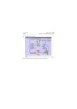
Air conditioner of this machine is vapor compression type refrigeration air conditioner, refer to
its working process and principle as follows:
(1) Compression process
Refrigerant absorbs heat in the evaporator and then changes into low-temperature low-pressure
refrigerant vapor, which is sucked into the compressor, where it is compressed into high-temperature
high-pressure refrigerant vapor, and then is discharged into the condenser.
(2) Condensation process
After high-temperature and high-pressure gaseous refrigerant enters condenser, the air, driven by
the engine radiator fan, passes across condenser surface to bring away heat of refrigerant. The
refrigerant is condensed into medium-temperature and high-pressure liquid type.
(3) Throttling process
Medium-temperature and high-pressure refrigerant liquid is filtered by dryer and then throttled
through the expansion valve (refrigerant is sprayed from the pores of expansion valve and expanded
suddenly). It changes into low-temperature and low-pressure refrigerant mist for entering the evapo-
rator.
(4) Evaporator process
Low-temperature and low-pressure refrigerant liquid formed by the throttling of expansion valve is
vaporized in the evaporator, the air in the car is driven by the evaporator fan unit to flow through the
evaporator surface. The refrigerant absorbs the heat of air in the car, thus to reduce the air tempera-
ture, and dissolve out condensate water. Refrigerant absorbing heat is evaporated into low-tempera-
ture and low-pressure refrigerant vapor, which is sucked into the compressor and compressed again,
so that one refrigeration cycle is completed.
The compressor keeps rotating, the above refrigeration process is cycled continuously. The heat in
the car is taken away by refrigerant in the evaporator, so as to complete cooling and dehumidification
of the complete vehicle.
Содержание CLG835H
Страница 2: ......
Страница 4: ...Contents January 24 2017 CLG835H...
Страница 6: ...1 2 General Information January 24 2017 CLG835H...
Страница 38: ...1 34 Machine Inspection Table January 24 2017 CLG835H...
Страница 154: ...2 116 Fault Diagnosis and Troubleshooting January 24 2017 Common fault code and troubleshooting CLG835H...
Страница 156: ...3 2 Power Train System January 24 2017 CLG835H...
Страница 214: ...3 2 Power Train System January 24 2017 CLG835H...
Страница 272: ...3 60 Testing and adjustment January 24 2017 Power Train Test CLG835H...
Страница 276: ...4 4 Hydraulic System January 24 2017 CLG835H...
Страница 296: ...4 24 Structure Function Principle January 24 2017 Work hydraulic system CLG835H Exploded view of control valve P18H00016...
Страница 297: ...4 25 January 24 2017 Structure Function Principle CLG835H Work hydraulic system Exploded view of control valve P18H00017...
Страница 308: ...4 36 Structure Function Principle January 24 2017 Work hydraulic system CLG835H Outline diagram of pilot valve P18H00027...
Страница 506: ...4 234 Fault Diagnosis and Troubleshooting January 24 2017 Common troubleshooting for brake system CLG835H...
Страница 552: ...6 2 Driver s Cab System January 24 2017 CLG835H...
Страница 606: ...6 56 Removal and Installation January 24 2017 Removal and installation of the engine hood torque mechanism CLG835H...
Страница 608: ...7 2 Structure January 24 2017 CLG835H...
Страница 662: ...8 4 Electrical System January 24 2017 CLG835H...
Страница 677: ...8 19 January 24 2017 Structure Function Principle CLG835H Power System P18E00014...
Страница 737: ...8 79 January 24 2017 Structure Function Principle CLG835H Audio system Audio system Audio system principle P18E00138...
Страница 756: ...9 2 Appendix January 24 2017 CLG835H...
Страница 757: ...9 3 January 24 2017 Schematic Diagram of Hydraulic System CLG835H Schematic Diagram of Hydraulic System...
Страница 758: ...9 4 January 24 2017 Schematic Diagram of Brake System CLG835H Schematic Diagram of Brake System...

