3-16
Structure Function Principle
January 24, 2017
Drive axle system
CLG835H
Drive axle system
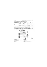
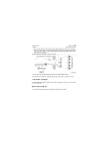
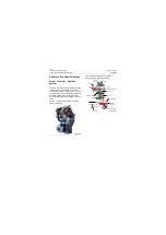
Composition and position of drive axle system
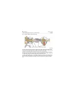
The basic function of drive axle for wheel loader is to reduce the gear box input speed with main drive
and wheel reducer and increase the torsion, thus to meet the requirements of driving, operating speed
and traction of the base machine. And also, change the straight line motion to vertical-lateral motion via
main drive, so that the drive wheel can be driven to rotate to make the base machine drive along the
straight route. The differential helps balance the speeds of left and right tires to make sure the machine
can still drive when the driving resistances on both sides are different.
In addition to basic features of drive axle for wheel loader, it is also a load-bearing unit for complete
machine, a support device for road wheel and mounting & support device for service brake. The drive
axle system mainly consists of front axle, rear axle and brake lines. The swing axle also includes front,
rear swing brackets, support shaft and other parts.
System technical parameters
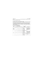
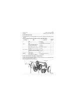
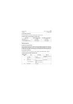
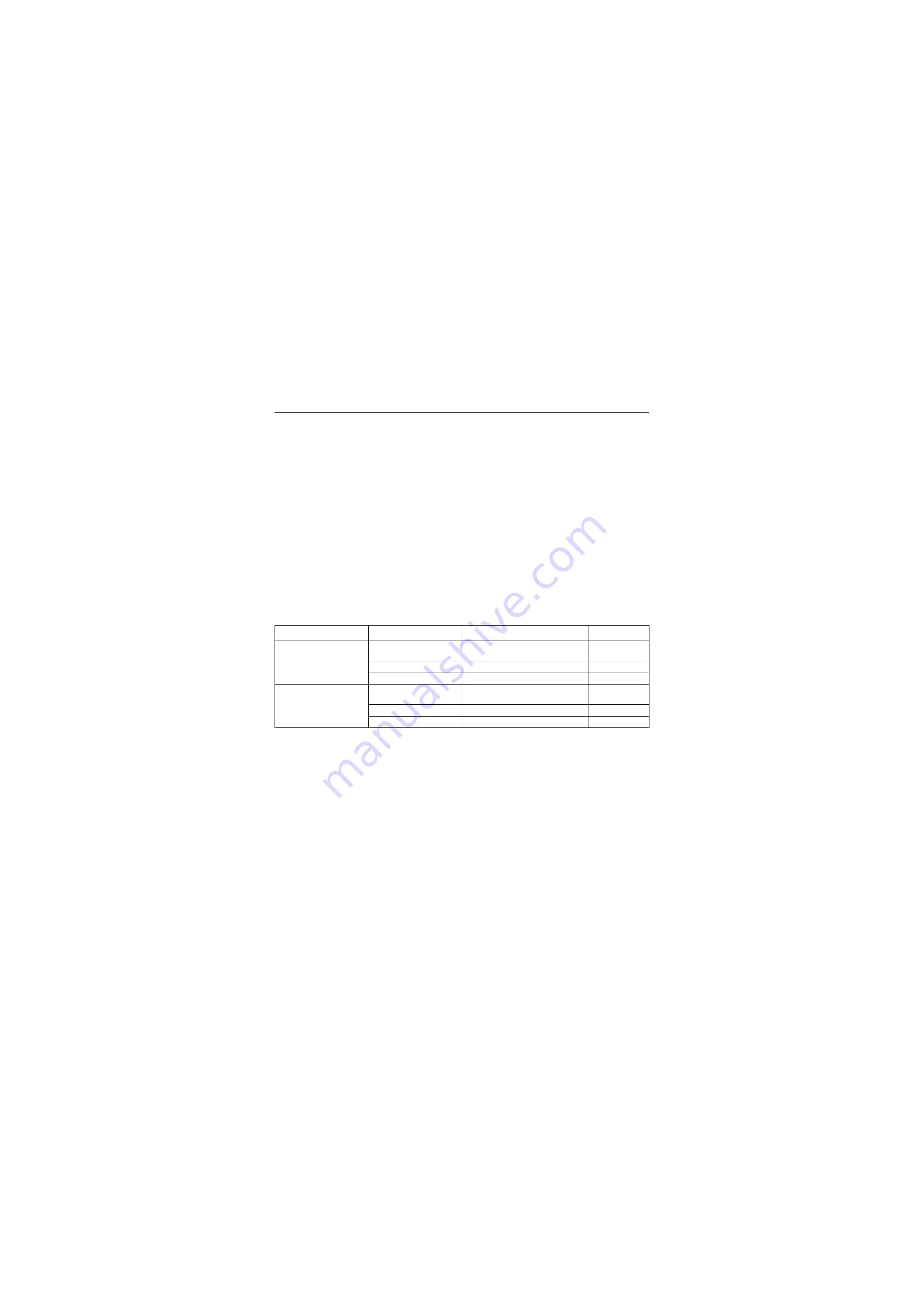
Major technical parameters for the drive axle system of this machine are listed in Table 3-4.
Table 3-4 Main technical parameter table for drive axle
System components
Items
Parameters
Remarks
Front axle
Drive mode
Spiral gear level-I reduction, wheel
planetary gear reduction
Brake mode
Built-in wet multi-plate type
Brake pressure /MPa\psi
1450
Rear axle
Drive mode
Spiral gear level-I reduction, wheel
planetary gear reduction
Brake mode
Built-in wet multi-plate type
Brake pressure /MPa\psi
1450
Содержание CLG835H
Страница 2: ......
Страница 4: ...Contents January 24 2017 CLG835H...
Страница 6: ...1 2 General Information January 24 2017 CLG835H...
Страница 38: ...1 34 Machine Inspection Table January 24 2017 CLG835H...
Страница 154: ...2 116 Fault Diagnosis and Troubleshooting January 24 2017 Common fault code and troubleshooting CLG835H...
Страница 156: ...3 2 Power Train System January 24 2017 CLG835H...
Страница 214: ...3 2 Power Train System January 24 2017 CLG835H...
Страница 272: ...3 60 Testing and adjustment January 24 2017 Power Train Test CLG835H...
Страница 276: ...4 4 Hydraulic System January 24 2017 CLG835H...
Страница 296: ...4 24 Structure Function Principle January 24 2017 Work hydraulic system CLG835H Exploded view of control valve P18H00016...
Страница 297: ...4 25 January 24 2017 Structure Function Principle CLG835H Work hydraulic system Exploded view of control valve P18H00017...
Страница 308: ...4 36 Structure Function Principle January 24 2017 Work hydraulic system CLG835H Outline diagram of pilot valve P18H00027...
Страница 506: ...4 234 Fault Diagnosis and Troubleshooting January 24 2017 Common troubleshooting for brake system CLG835H...
Страница 552: ...6 2 Driver s Cab System January 24 2017 CLG835H...
Страница 606: ...6 56 Removal and Installation January 24 2017 Removal and installation of the engine hood torque mechanism CLG835H...
Страница 608: ...7 2 Structure January 24 2017 CLG835H...
Страница 662: ...8 4 Electrical System January 24 2017 CLG835H...
Страница 677: ...8 19 January 24 2017 Structure Function Principle CLG835H Power System P18E00014...
Страница 737: ...8 79 January 24 2017 Structure Function Principle CLG835H Audio system Audio system Audio system principle P18E00138...
Страница 756: ...9 2 Appendix January 24 2017 CLG835H...
Страница 757: ...9 3 January 24 2017 Schematic Diagram of Hydraulic System CLG835H Schematic Diagram of Hydraulic System...
Страница 758: ...9 4 January 24 2017 Schematic Diagram of Brake System CLG835H Schematic Diagram of Brake System...

