3-5
January 24, 2017
Basic Information
CLG835H
System schematic diagram and working principle description
System schematic diagram and working principle description
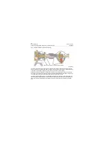
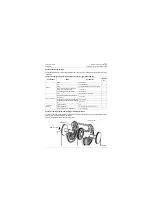
The torque converter -gearbox assembly equipped in this machine is ZF 4WG158 full auto type, and the
drive axle is 30 wet axle, whose structure diagram are shown as below:
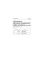
Tire
Tire structure
Radial tire
Tubeless bias tire or tubed bias
tire is optional
Specification
17.5R25 two star L3
Level
\
Type of tread
L-3
Ordinary block
Rim
Specification
25-14.00/1.5
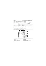
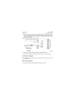
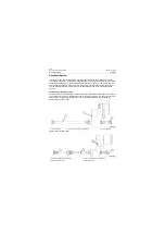
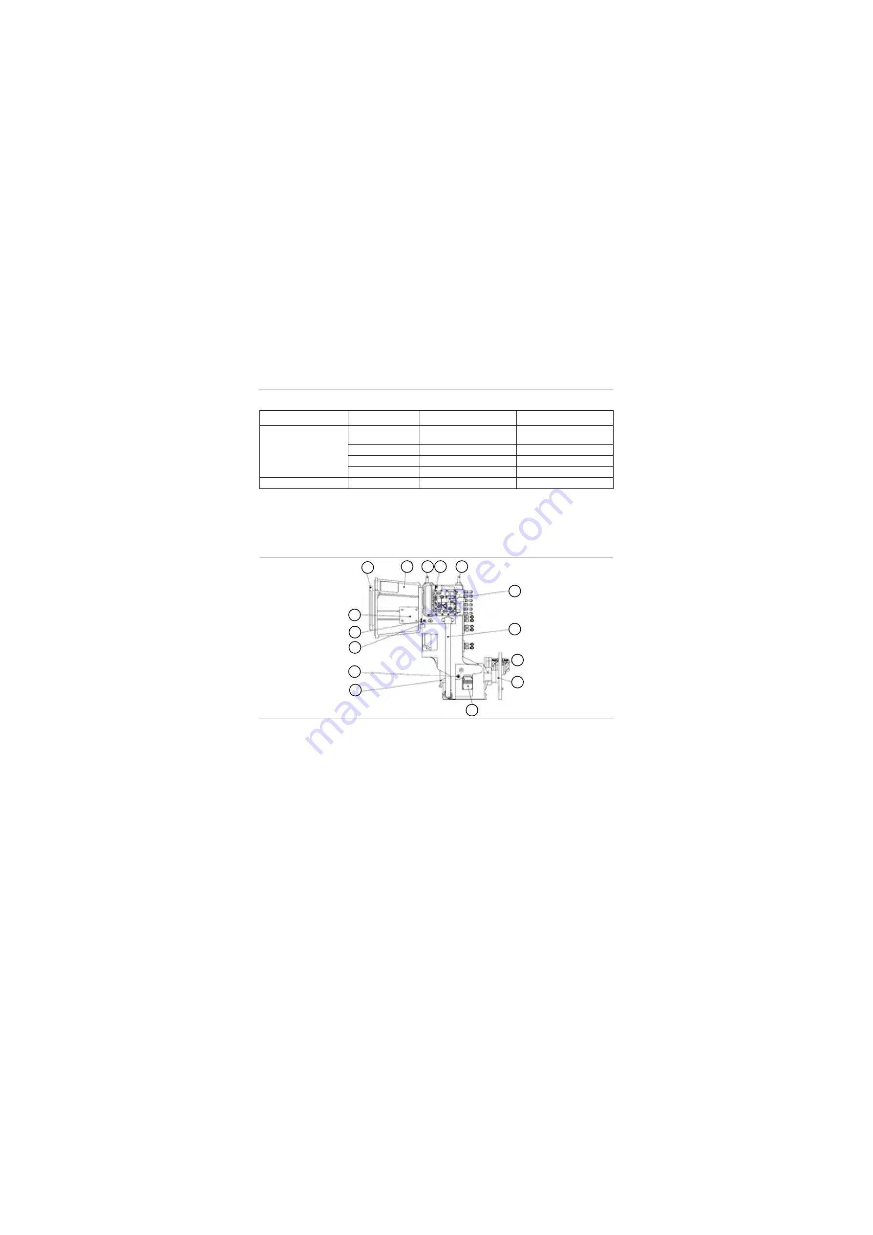
Figure 3-2 Diagram for gear box assembly composition
1. Coupling device
2. Torque converter housing
3. Lifting eye
4. Control harness interface
5. Electro-hydraulic shift control valve
6. Suction tube
7. Brake
8. Output plate
9. Nameplate
10.Output flange
11.Speed sensor
12.Oil outlet of torque converter
13.Torque converter outlet oil temperature sensor
14.Cover
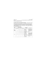
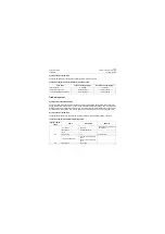
Table 3-1: Main technical parameter table for power train system
System components
Items
Parameters
Remarks
1
2
3
3
5
6
7
8
9
10
11
12
13
14
4
P18T00002
Содержание CLG835H
Страница 2: ......
Страница 4: ...Contents January 24 2017 CLG835H...
Страница 6: ...1 2 General Information January 24 2017 CLG835H...
Страница 38: ...1 34 Machine Inspection Table January 24 2017 CLG835H...
Страница 154: ...2 116 Fault Diagnosis and Troubleshooting January 24 2017 Common fault code and troubleshooting CLG835H...
Страница 156: ...3 2 Power Train System January 24 2017 CLG835H...
Страница 214: ...3 2 Power Train System January 24 2017 CLG835H...
Страница 272: ...3 60 Testing and adjustment January 24 2017 Power Train Test CLG835H...
Страница 276: ...4 4 Hydraulic System January 24 2017 CLG835H...
Страница 296: ...4 24 Structure Function Principle January 24 2017 Work hydraulic system CLG835H Exploded view of control valve P18H00016...
Страница 297: ...4 25 January 24 2017 Structure Function Principle CLG835H Work hydraulic system Exploded view of control valve P18H00017...
Страница 308: ...4 36 Structure Function Principle January 24 2017 Work hydraulic system CLG835H Outline diagram of pilot valve P18H00027...
Страница 506: ...4 234 Fault Diagnosis and Troubleshooting January 24 2017 Common troubleshooting for brake system CLG835H...
Страница 552: ...6 2 Driver s Cab System January 24 2017 CLG835H...
Страница 606: ...6 56 Removal and Installation January 24 2017 Removal and installation of the engine hood torque mechanism CLG835H...
Страница 608: ...7 2 Structure January 24 2017 CLG835H...
Страница 662: ...8 4 Electrical System January 24 2017 CLG835H...
Страница 677: ...8 19 January 24 2017 Structure Function Principle CLG835H Power System P18E00014...
Страница 737: ...8 79 January 24 2017 Structure Function Principle CLG835H Audio system Audio system Audio system principle P18E00138...
Страница 756: ...9 2 Appendix January 24 2017 CLG835H...
Страница 757: ...9 3 January 24 2017 Schematic Diagram of Hydraulic System CLG835H Schematic Diagram of Hydraulic System...
Страница 758: ...9 4 January 24 2017 Schematic Diagram of Brake System CLG835H Schematic Diagram of Brake System...

