Rev: 06.29.22
Page 3
CCD-0004431
Unit MUST be supported per manufacturer's recommendations before working underneath. Failure
to do so may result in death or serious personal injury.
The “CAUTION” symbol above is a sign that a safety risk is involved and may cause personal injury
and/or product or property damage if not safely adhered to and within the parameters set forth
in this manual
Always wear eye protection when performing service, maintenance or installation procedures.
Other safety equipment to consider would be hearing protection, gloves and possibly a full face
shield, depending on the nature of the task.
Moving parts can pinch, crush or cut. Keep clear and use caution.
No repairs should be attempted by anyone other than a qualified professional. The deployment and
retraction of the step assembly can cause injury if proper precautions are not taken. The step
assembly was designed for an operational weight rating of 400 lbs.
Resources Required
• 1 to 2 people, depending on task
• Cordless or electric drill or screw gun
• Appropriate drive bit
• Tape measure
• #10 - 1 1/2" wood screws (wood floor)
• #10 - 1 1/2" self-tapping screws (laminate floor)
• #10 flat head screws
• Non -permanent method of marking
• Temporary Pin or tool 3/16” in diameter
• Materials for framing out penetration for lift assist.
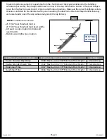
Door Frame
Inner Flange
Door Frame
Inner Flange
There are two tread widths currently available, 23.5” (24” door jamb min.) or 27.5” (28” door jamb min.).
Record the measurement of the door frame inner flange to door frame inner flange (Fig. 1) to determine
which tread width to use.
SolidStep
®
Levitate Tread Width and Floor Height Variations
Fig. 1
Measure
Содержание SolidStep Levitate
Страница 1: ...SolidStep Levitate OEM INSTALLATION MANUAL...


