background image

Rev: 08.17.21 


Page 9

CCD-0004406

Note:  

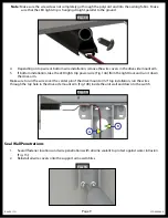
Make sure the screw does not completely go through the polycord and into the awning fabric.  Make 

sure that the LED light strip is hanging straight, parallel to the ground.

Fig. 13 

Fig. 15 

B

A

Fig. 14 

4. 

Depending on top wire or bottom wire installation, remove the wire covers in the drive side mount arm.

5. 

If bottom installation, take the LED light strip power wire (Fig. 14A) from the light track and run it down 

the drive arm. 

Make sure to run the wires over the center pin of the drive mount arm. If top installation, run the wires 

through the top hole in the drive side mount arm (Fig. 14B) inside the unit wall and down to the switch.

Seal Wall Penetrations

1. 

Seal all fastener locations and wire penetrations with silicone sealant to protect against water intrusion 

(Fig. 15).

2. 

Reinstall all wire covers onto the support arm assemblies.

Содержание Solera 5000 Series

Страница 1: ...Solera 5000 Series Awning OEM INSTALLATION MANUAL...

Страница 2: ...he degree of difficulty operation and ability of the individual performing the instructions This manual cannot begin to plot out instructions for every possibility but provides the general instruction...

Страница 3: ...ubricant Installation Awning Rail Installation Note Awning rail supplied separately 1 Position the awning rail along the line where the roof and wall meet or A For pitched awnings a minimum of 6 above...

Страница 4: ...il down to the floor line This is the centerline of the support arm assembly Fig 2 3 Insert the drive head assembly shaft into the end cap Fig 3 A Align the holes and secure with waxed screw B Repeat...

Страница 5: ...p against the bottom of the awning rail and attach it to the side of the unit with two 14 x 1 1 4 screws at the top Fig 5 and one screw at the bottom Fig 6 Note Make sure the awning assembly is square...

Страница 6: ...sembly 2 Connect wiring from the unit to the switch and the awning drive head per the wiring diagram Fig 9 Note Check the switch If the awning is running in reverse of what the switch indicates revers...

Страница 7: ...ppert Rocker Switch Fig 9 15A Circuit Breaker per RVIA Code OEM Supplied Red Black Manual Rocker Switch Blue Red Awning Motor Battery Power Source or Converter White Fig 10 Ground Power 2 3 1 4 5 6 Wi...

Страница 8: ...Connect the black wire from the light side to the ground wire from the unit side Note The LED light rail must be wired through a 3 amp maximum fused circuit LED Light Strip Note Awning MUST be extend...

Страница 9: ...arm 5 If bottom installation take the LED light strip power wire Fig 14A from the light track and run it down the drive arm Make sure to run the wires over the center pin of the drive mount arm If to...

Страница 10: ...ntative has been provided Any unauthorized use shall void any applicable warranty The information contained in this manual is subject to change without notice and at the sole discretion of LCI Revised...

Отзывы: