


9
432-LIPPERT (432-547-7378)
Rev: 08.29.22
Quick Drop Stabilizer
Installation and Owner’s Manual
(For Aftermarket Applications)
CCD-0004455
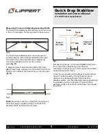
NOTE:
Do not weld Quick Drop Stabilizers to the trailer.
Welding the system to the trailer voids all warranty claims.
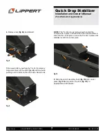
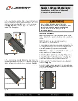
1.
Make sure trailer is parked and wheels are chocked.
2.
Manually crank the system upward to place the
stabilizers under the trailer as need be.
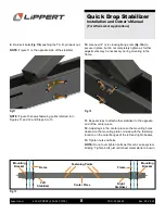
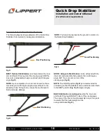
3.
Mount stabilizer assembly across the trailer, from frame
to frame, and center
(Fig. 14)
. The stabilizer mounting
brackets should equally extend over and outward from
the frame as determined
(Fig. 15A)
. Make sure stabilizer
assembly is center and mounting brackets are extending
equal distance.
B
A
A
A
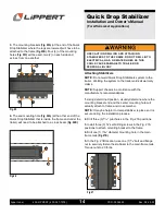
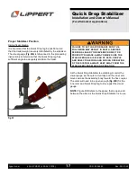
NOTE:
Figure 14 shows Quick Drop Stabilizer upside
down, as if the looking from the ground up underneath
trailer. Figure 16 shows Quick Drop Stabilizer from a
horizontal view to provide clarity.
Mounting Plates
Fig.14
Fig.15
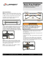
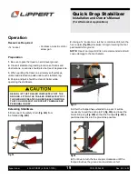
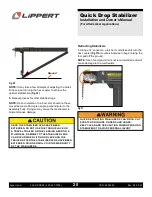
4.
Drill six (6)
5/16
" pilot holes, three (3) per end, in the
Fig. 17A positions.
5.
Install six (6)
3/8
” self-drilling screws, three (3) per end, in
the Fig. 17A positions.
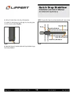
6.
Drill two (2)
25/64
” holes, one (1) per end), in the Fig. 17B
positions.
7.
Using two (2)
3/8
” bolts and flange nuts, securely fasten
the stabilizer to the main frame rails with two bolts and
nuts, one (1) per end, per mounting bracket in the Fig. 17B
locations. Torque nuts to 23 ft-lbs.
Attaching Stabilizers
A
Fig.16
Fig.17
Center
Piece
Ground
Frame Area
Frame Area
NOTE:
It may be helpful to clamp stabilizer in place to
secure during the installation process.
USE CAUTION DRILLING AND ATTACHING
STABILIZERS TO THE FRAME. DO NOT DRILL INTO
ELECTRICAL, GAS, OR WATER LINES AS THIS
COULD CAUSE DAMAGE TO TRAILER OR
PERSONAL INJURY.


