¸
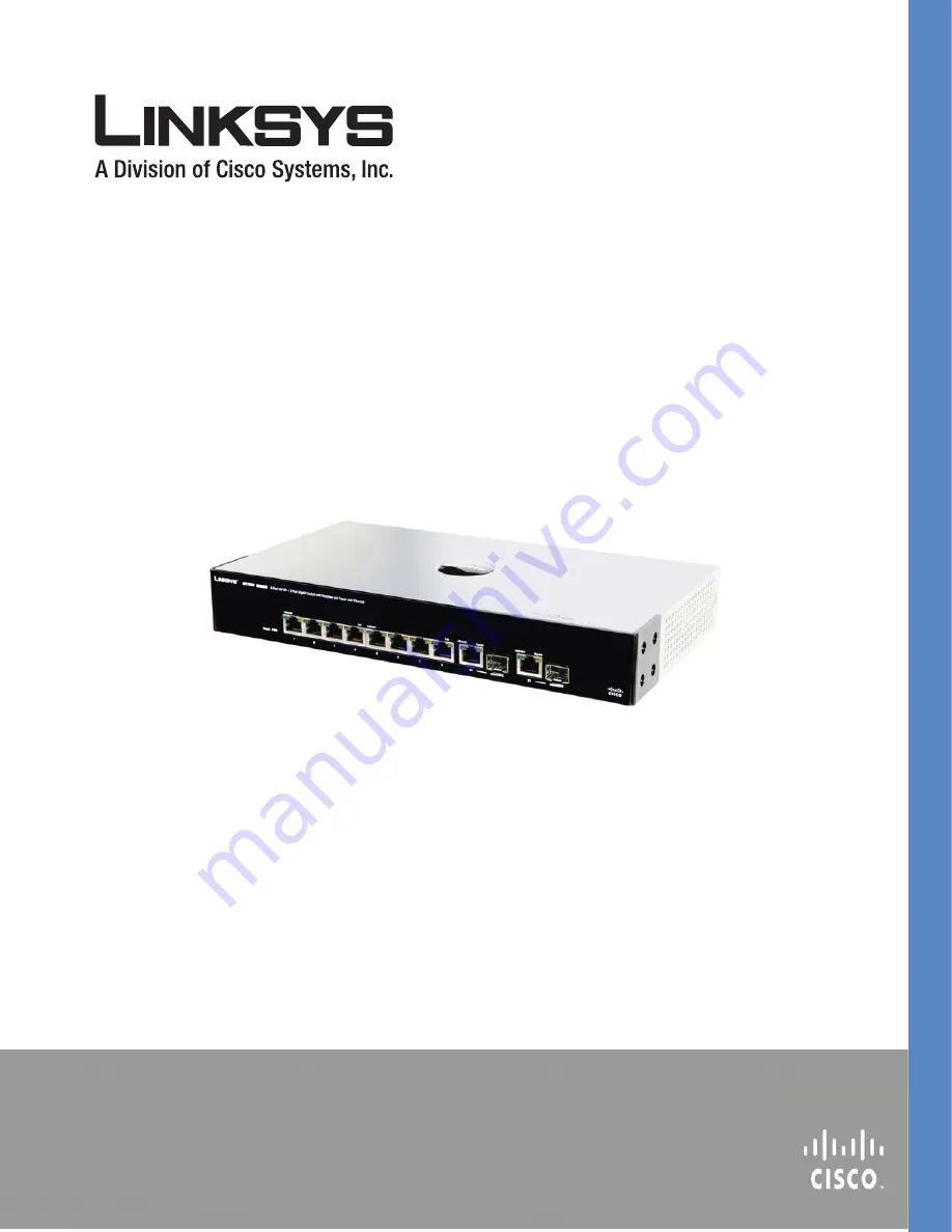
SFE1000P 8-port 10/100 Ethernet Switch with PoE Administration Guide
SFE1
000P 8
-POR
T 10/1
00 ETH
ER
NET SW
ITCH
WITH
PO
E ADM
INISTRATION G
U
ID
E
March 2008
Страница 1: ...P 8 port 10 100 Ethernet Switch with PoE Administration Guide SFE1000P 8 PORT 10 100 ETHERNET SWITCH WITH POE ADMINISTRATION GUIDE SFE1000P 8 port 10 100 Ethernet Switch with PoE Administration Guide March 2008 ...
Страница 2: ...ksys the Cisco Systems logo the Linksys Logo and the Linksys One logo are registered trademarks of Cisco Systems Inc All other trademarks mentioned in this document are the property of their respective owners Document Revision History Revision Date Description 1 0 March 2008 Initial release ...
Страница 3: ... Defining General System Information 11 Resetting the Device 11 Chapter 4 Managing Power over Ethernet Devices 13 Defining PoE Settings 13 Chapter 5 Configuring Device Security 15 Passwords Management 15 Modifying the Local User Settings 17 Defining Authentication 17 Defining Authentication Profiles 18 Modify the Authentication Profile 19 Mapping Authentication Profiles 19 Defining TACACS 20 Modif...
Страница 4: ...es 44 Defining Port Settings 44 Modifying Port Settings 44 Defining LAG Management 45 Modifying LAG Membership 47 Defining LAG Settings 48 Configuring LACP 49 Modify LACP Parameter Settings 50 Chapter 7 Configuring VLANs 51 Defining VLAN Properties 52 Modifying VLANs 53 Defining VLAN Membership 53 Modifying VLAN Membership 54 Defining Interface Settings 54 Modifying VLAN Interface Settings 55 Conf...
Страница 5: ... Defining Rapid Spanning Tree 78 Modifying RTSP 79 Defining Multiple Spanning Tree 79 Defining MSTP Properties 80 Mapping MSTP Instances to VLAN 81 Defining MSTP Instance Settings 82 Defining MSTP Interface Settings 83 Chapter 12 Configuring SNMP 85 Configuring SNMP Security 86 Defining the SNMP Engine ID 86 Defining SNMP Views 87 Defining SNMP Users 88 Modifying SNMP Users 89 Define SNMP Groups 8...
Страница 6: ...gement Overview 114 File Management 115 Firmware Upgrade 115 Save Configuration 116 Copy Files 117 Active Image 118 Chapter 15 Managing System Logs 119 Enabling System Logs 119 Viewing the Device Memory Logs 121 Clearing Message Logs 121 Viewing the Flash Logs 122 Clearing Message Logs 122 Viewing Remote Logs 123 Modify Syslog Server Settings 124 Chapter 16 Configuring System Time 125 Defining Sys...
Страница 7: ...guring Port Mirroring 142 Modifying Port Mirroring 143 Defining CPU Utilization 143 Appendix A Console Interface Configuration 144 Overview 144 Configuring the HyperTerminal Application 144 Connecting to the SFE1000P through a Telnet Session 147 Appendix B Contacts 148 US Canada Contacts 148 EU Contacts 148 Appendix C Warranty Information 149 LIMITED WARRANTY 149 Exclusions and Limitations 149 Obt...
Страница 8: ...ndix F Safety Information 162 Meaning of the Warning Symbol 162 General Safety Information 162 Appendix G Software License Agreement 164 Software in Linksys Products 164 Software Licenses 164 Schedule 1 Linksys Software License Agreement 164 Schedule 2 166 Schedule 3 171 ...
Страница 9: ...on Chapter 4 Managing Power over Ethernet Devices describes configuring PoE settings Chapter 5 Configuring Device Security describes password management defining authentication access method traffic control 802 1x protocols access control and Denial of service prevention Chapter 6 Configuring Device Interfaces describes defining port settings LAG management LAG settings and configuring LACP Chapte...
Страница 10: ...s view device memory logs flash logs and remote logs Chapter 16 Configuring System Time provides information for configuring the system time and includes defining system time SNTP settings and SNTP authentication Chapter 17 Viewing Statistics describes viewing and managing device statistics for RMON interfaces GVRP EAP and Etherlike statistics Chapter 18 Managing Device Diagnostics contains inform...
Страница 11: ...uttons Using Screen and Table Options Resetting the Device Logging Off The Device The following diagram illustrates how the SFE1000P fits into your network Starting the Application This section contains information for starting the Linksys User Interface To open the User Interface 1 Open a web browser 2 Enter the device s IP address in the address bar and press Enter An Enter Network Password Page...
Страница 12: ...t password and can be configured without entering a password Passwords are both case sensitive and alpha numeric 4 Click Login The Embedded Web System Home Page opens NOTE If you have logged in automatically via the Service Router user interface the Tree and Device views appear and allow you to navigate through the various areas of the web interface However the following page will appear within th...
Страница 13: ...ble device features The main branches expand to provide the subfeatures 2 Device View The device view provides information about device ports current configuration and status table information and feature components The device view also displays other device information and dialog boxes for configuring parameters 3 Table Area The Table area enables navigating through the different device features ...
Страница 14: ...tion Provides an explanation of the Linksys user interface buttons including both management buttons and task icons Using the Linksys Management Buttons Provides instructions for adding modifying and deleting device parameters Device Representation The Linksys home page displays a graphical representation of the device Device Representation The Linksys home page contains a graphical SFE1000 and SF...
Страница 15: ...ing devices This section contains the following topics Adding Device Information Modifying Device Information Deleting Device Information Adding Device Information User defined information can be added to specific EWS pages by opening a new Add page To add information to tables or EWS pages Button Name Button Description Apply Applies changes to the device Clear Counters Clears statistic counters ...
Страница 16: ...Click Apply The configuration information is saved and the device is updated Modifying Device Information 1 Open the EWS page 2 Select a table entry 3 Click the Edit Button A Modify page opens for example the Interface Priority Page opens Edit Interface Priority 4 Define the fields 5 Click Apply The fields are modified and the information is saved to the device Deleting Device Information 1 Open t...
Страница 17: ...vice This prevents the current device configuration from being lost To reset the device 1 Click System General Reset The Reset page opens Reset Page 2 Click the Reset button The device is reset and a prompt for a user name and password is displayed 3 Enter a user name and password to reconnect to the Web Interface if the device is not part of a full Linksys One system If the device is part of a Li...
Страница 18: ...ystem information This section contains the following topics Understanding the Device Zoom View Defining General System Information Resetting the Device Understanding the Device Zoom View The Zoom Page is the main window used for viewing the device To open the Zoom Page Click the System System Management Zoom The Zoom Page opens Zoom Page The Zoom Page contains the following port indicators Green ...
Страница 19: ...ck the System System Management System Information The System Information Page opens System Information Page 2 Enter information into the appropriate fields and press Apply Resetting the Device The Reset page enables the device to be reset from a remote location Save all changes to the Startup Configuration file before resetting the device This prevents the current device configuration from being ...
Страница 20: ...SFE1000P Gigabit Ethernet Switch Administration Guide Chapter 3 Reset Page 2 Click the Reset button 3 Enter a user name and password to reconnect to the Web Interface If the device is part of a Linksys One system login is automatically done from the Service Router ...
Страница 21: ...vices which receive power from the device power supplies for example IP phones Powered Devices are connected to the device via Ethernet ports Guard Band protects the device from exceeding the maximum power level For example if 400W is maximum power level and the Guard Band is 20W if the total system power consumption exceeds 380W no additional PoE components can be added The accumulated PoE compon...
Страница 22: ...efining PoE Settings SFE1000P Gigabit Ethernet Switch Administration Guide Chapter 4 PoE Settings Page 2 Click the Edit button The Edit PoE opens Edit PoE 3 Define the relevant fields 4 Click Apply The PoE Settings are defined and the device is updated ...
Страница 23: ...thod Defining Traffic Control Defining 802 1x Defining Access Control Defining DoS Prevention Passwords Management This section contains information for defining passwords Passwords are used to authenticate users accessing the device 1 Click Security Suite Passwords Management User Authentication The User Authentication Page opens NOTE By default a single user name is defined admin with no passwor...
Страница 24: ...Management SFE1000P Gigabit Ethernet Switch Administration Guide Chapter 5 User Authentication Page 2 Click the Add button The Add Local User Page opens Add Local User Page 3 Define the relevant fields 4 Click Apply The local user settings are modified ...
Страница 25: ...er Authentication The User Authentication Page Opens 2 Click the Edit Button The Edit Local User Page opens Edit Local User Page 3 Define the relevant fields 4 Click Apply The local user settings are modified and the device is updated Defining Authentication The Authentication section contains the following pages Defining Authentication Profiles Mapping Authentication Profiles Defining TACACS Defi...
Страница 26: ...ion occurs in the order the methods are selected If the first authentication method is not available the next selected method is used For example if the selected authentication methods are RADIUS and Local and the RADIUS server is not available then the user is authenticated locally 1 Click Security Suite Authentication Profiles The Profiles Page opens Profiles Page 2 Click the Add button The Add ...
Страница 27: ... and the device is updated Mapping Authentication Profiles After authentication profiles are defined they can be applied to management access methods For example console users can be authenticated by one authentication profile while Telnet users are authenticated by another authentication profile Authentication methods are selected using arrows The order in which the methods are selected is the or...
Страница 28: ...rocesses TACACS provides the following services Authentication Provides authentication during login and via user names and user defined passwords Authorization Performed at login Once the authentication session is completed an authorization session starts using the authenticated user name The TACACS server checks the user privileges The TACACS protocol ensures network integrity through encrypted p...
Страница 29: ...ch Administration Guide Chapter 5 To define TACACS 1 Click Security Suite Authentication TACACS The TACACS Page opens TACACS Page 2 Click The Add button The Add TACACS Server Page opens Add TACACS Server Page 3 Add a TACACS server 4 Click Apply The TACACS server is added and the device is updated ...
Страница 30: ...ply The TACACS settings are modified and the device is updated Defining RADIUS Remote Authorization Dial In User Service RADIUS servers provide additional security for networks RADIUS servers provide a centralized authentication method for web access The default parameters are user defined and are applied to newly defined RADIUS servers If new default parameters are not defined the system default ...
Страница 31: ...ication SFE1000P Gigabit Ethernet Switch Administration Guide Chapter 5 RADIUS Page 2 Click the Add button The Add Radius Server Page opens Add Radius Server Page 3 Define the relevant fields 4 Click Apply The Radius Server is added and the device is updated ...
Страница 32: ...IUS Server settings are modified and the device is updated Defining Access Method The access method section contains the following pages Defining Access Profiles Defining Profile Rules Defining Access Profiles Access profiles are profiles and rules for accessing the device Access to management functions can be limited to user groups User groups are defined for interfaces according to IP addresses ...
Страница 33: ...p 2 can access the switch module via both HTTPS and Telnet sessions The Access Profile Page contains the currently configured access profiles and their activity status Assigning an access profile to an interface denies access via other interfaces If an access profile is assigned to any interface the device can be accessed by all interfaces To define access profiles 1 Click Security Suite Access Me...
Страница 34: ...lick Apply The access profile is added and the device is updated Defining Profile Rules Access profiles can contain up to 128 rules that determine which users can manage the switch module and by which methods Users can also be blocked from accessing the device Rules are composed of filters including Rule Priority Interface Management Method IP Address Prefix Length Forwarding Action ...
Страница 35: ...de Chapter 5 To define profile rules 1 Click Security Suite Access Method Profile Rules The Profile Rules Page opens Profile Rules Page 2 Click the Add button The Add Profile Rule Page opens Add Profile Rule Page 3 Define the relevant fields 4 Click Apply The profile rule settings are added and the device is updated ...
Страница 36: ...tration Guide Chapter 5 Modifying Profile Rules 1 Click Security Suite Access Method Profile Rules The Profile Rules Page opens 2 Click the Edit button The Edit Profile Rule Page opens Edit Profile Rule Page 3 Define the relevant fields 4 Click Apply The profile rules are defined and the device is updated ...
Страница 37: ...result of an excessive amount of broadcast messages simultaneously transmitted across a network by a single port Forwarded message responses are heaped onto the network straining network resources or causing the network to time out Storm Control is enabled per all ports by defining the packet type and the rate the packets are transmitted The system measures the incoming Broadcast and Multicast fra...
Страница 38: ...e received on specific ports Access to the locked port is limited to users with specific MAC addresses These addresses are either manually defined on the port or learned on that port up to the point when it is locked When a packet is received on a locked port and the packet source MAC address is not tied to that port either it was learned on a different port or it is unknown to the system the prot...
Страница 39: ...ty The Port Security Page opens Port Security Page 2 Define the relevant fields 3 Click Apply Port security is defined and the device is updated Modifying Port Security 1 Click Security Suite Traffic Control Port Security The Port Security Page opens 2 Click the Edit Button The Edit Port Security Page opens Edit Port Security Page 3 Modify the relevant fields 4 Click Apply Port security is modifie...
Страница 40: ...access the system services Authentication Server Specifies the external server for example the RADIUS server that performs the authentication on behalf of the authenticator and indicates whether the supplicant is authorized to access system services Port based authentication creates two access states Controlled Access Permits communication between the supplicant and the system if the supplicant is...
Страница 41: ...opens 802 1X Properties Page 2 Define the relevant fields 3 Click Apply The 802 1X properties are defined and the device is updated Defining Port Authentication 1 Click Security Suite 802 1X Port Authentication The 802 1X Properties Page opens 802 1X Port Authentication Page 2 Define the relevant fields 3 Click Apply The port authentication settings are modified and the device is updated ...
Страница 42: ...r 5 Modifying 8021X Security 1 Click Security Suite 802 1X Properties The 802 1X Properties Page opens 2 Click the Edit button The Port Authentication Settings Page opens Port Authentication Settings Page 3 Modify the relevant fields 4 Click Apply The port authentication settings are defined and the device is updated ...
Страница 43: ...ecurity Suite 802 1X Multiple Host The 802 1X Multiple Host Page opens 802 1X Multiple Host Page 2 Define the relevant fields 3 Click Apply The host settings are modified and the device is updated Modifying Multiple Host Settings 1 Click Security Suite 802 1X Multiple Host The 802 1X Properties Page opens 2 Click the Edit button The Edit Multiple Host Page opens Edit Multiple Host Page 3 Modify th...
Страница 44: ...pdated Defining Access Control Access Control Lists ACL allow network managers to define classification actions and rules for specific ingress ports Your switch supports up to 256 ACLs Packets entering an ingress port with an active ACL are either admitted or denied entry If they are denied entry the user can disable the port ACLs are composed of access control entries ACEs that are made of the fi...
Страница 45: ...defined The table lists Access Control Elements ACE rules which can be added only if the ACL is not bound to an interface To define the MAC Based ACL 1 Click Security Suite Access Control MAC Based ACL The MAC Based ACL Page opens MAC Based ACL Page 2 Click the Add ACL button The Add MAC Based ACL Page opens Add MAC Based ACL Page 3 Define the relevant fields 4 Click Apply The MAC Based ACL is def...
Страница 46: ... ACL 1 Select an existing ACL 2 Click the Add Rule button The Add MAC Based Rule Page opens Add MAC Based Rule Page 3 Define the relevant fields 4 Click Apply The ACL Rule is defined and the device is updated Defining IP Based ACL The IP Based ACL Page contains information for defining IP Based ACLs including defining the ACEs defined for IP Based ACLs ...
Страница 47: ...dministration Guide Chapter 5 1 Click Security Suite Access Control IP Based ACL The IP Based ACL Page opens IP Based ACL Page 2 Click the Add Button The Add IP Based ACL Page opens Add IP Based ACL Page 3 Define the relevant fields 4 Click Apply The IP Based ACL is defined and the device is updated ...
Страница 48: ...IP Based Rule Page opens Add IP Based Rule Page 3 Select either Match DSCP or Match IP 4 Click Apply The IP based rule settings are modified and the device is updated Defining ACL Binding When an ACL is bound to an interface all the ACE rules that have been defined are applied to the selected interface Whenever an ACL is assigned on a port or a LAG flows from that ingress interface that do not mat...
Страница 49: ...Apply The ACL binding settings are modified and the device is updated Modifying ACL Binding 1 Click Security Suite Access Control ACL Binding The ACL Binding Page opens 2 Click the Edit button The Edit ACL Binding Page opens Edit ACL Binding Page 3 Define the relevant fields 4 Click Apply ACL binding is defined and the device is updated Defining DoS Prevention The DoS Prevention section contains t...
Страница 50: ... Security Suite Dos Prevention Global Settings The Global Settings Page opens Global Settings Page 2 Define the relevant fields 3 Click Apply The Dos prevention global settings are defined and the device is updated Defining Martian Addresses 1 Click Security Suite Dos Prevention Martian Addresses The Martian Addresses Page opens Martian Addresses Page ...
Страница 51: ...vention SFE1000P Gigabit Ethernet Switch Administration Guide Chapter 5 2 Click the Add button The Add Martian Addresses Page opens Add Martian Addresses Page 3 Define the relevant fields 4 Click Apply The martian addresses are added and the device is updated ...
Страница 52: ...fining LAG Settings Configuring LACP Defining Port Settings The Port Settings Page contains fields for defining port parameters To define port settings 1 Click Bridging Port Management Port Settings The Port Settings Page opens Port Settings Page 2 Define the relevant fields 3 Click Apply Port Settings are defined and the device is updated Modifying Port Settings 1 Click Bridging Port Management P...
Страница 53: ...ting ports multiplies the bandwidth between the devices increases port flexibility and provides link redundancy The device supports both static LAGs and Link Aggregation Control Protocol LACP LAGs LACP LAGs negotiate aggregating port links with other LACP ports located on a different device If the other device ports are also LACP ports the devices establish a LAG between them Ensure the following ...
Страница 54: ...LAG have the same transceiver type The device supports up to 8 LAGs and eight ports in each LAG Ports can be configured as LACP ports only if the ports are not part of a previously configured LAG Ports added to a LAG lose their individual port configuration When ports are removed from the LAG the original port configuration is applied to the ports To define LAG management 1 Click Bridging Port Man...
Страница 55: ...dit button The Edit LAG Membership Page opens Edit LAG Membership Page 3 Define the relevant fields 4 To assign ports to a LAG click the port numbers in the Port List and then click the Right Arrow button The port number then appears in the LAG Members list Conversely to remove a port from a LAG click the port number in the LAG Members list and then click the Left Arrow button 5 Click Apply The LA...
Страница 56: ...e aggregated group Link aggregated groups multiply the bandwidth between the devices increase port flexibility and provide link redundancy The LAG Settings Page contains fields for configuring parameters for configured LAGs The device supports up to eight ports per LAG and eight LAGs per system 1 Click Bridging Port Management LAG Settings The LAG Settings Page opens LAG Settings Page 2 Click the ...
Страница 57: ...the device is updated Configuring LACP Aggregate ports can be linked into link aggregation port groups Each group is comprised of ports with the same speed set to full duplex operations Aggregated Links can be manually setup or automatically established by enabling Link Aggregation Control Protocol LACP on the relevant links Aggregate ports can be linked into link aggregation port groups Each grou...
Страница 58: ...P Page opens LACP Page 2 Define the relevant fields 3 Click Apply The LACP settings are modified and the device is updated Modify LACP Parameter Settings 1 Click Bridging Port Managing LACP The LACP Page opens 2 Click the Edit button The Edit LACP Page opens Edit LACP Page 3 Define the relevant fields 4 Click Apply The LACP Parameters settings are defined and the device is updated ...
Страница 59: ...c within the VLAN a Layer 3 router working at a protocol level is required to allow traffic flow between VLANs Layer 3 routers identify segments and coordinate with VLANs VLANs are Broadcast and Multicast domains Broadcast and Multicast traffic is transmitted only in the VLAN in which the traffic is generated VLAN tagging provides a method of transferring VLAN information between VLAN groups VLAN ...
Страница 60: ...LAN Properties Page provides information and global parameters for configuring and working with VLANs 1 Click Bridging VLAN Management Properties The Properties Page opens Properties Page 2 Click the Add button The Add VLAN Page opens Add VLAN Page 3 Define the relevant fields 4 Click Apply The add VLAN settings are modified and the device is updated ...
Страница 61: ...fine the relevant fields 4 Click Apply The VLAN Settings are defined and the device is updated Defining VLAN Membership The VLAN Membership Page contains a table that maps VLAN parameters to ports Ports are assigned VLAN membership by toggling through the Port Control settings 1 Click Bridging VLAN Management Membership The VLAN Membership Page opens Membership Page 2 Define the relevant fields 3 ...
Страница 62: ...e 3 Define the relevant fields 4 Click Apply VLAN Membership is modified and the device is updated Defining Interface Settings The VLAN Interface Setting Page provides parameters for managing ports that are part of a VLAN The port default VLAN ID PVID is configured on the VLAN Port Settings page All untagged packets arriving to the device are tagged by the ports PVID 1 Click Bridging VLAN Manageme...
Страница 63: ...rts Page 3 Define the relevant fields 4 Click Apply The VLAN Interface settings are modified and the device is updated Configuring GVRP Settings GARP VLAN Registration Protocol GVRP is specifically provided for automatic distribution of VLAN membership information among VLAN aware bridges GVRP allows VLAN aware bridges to automatically learn VLANs to bridge ports mapping without having to individu...
Страница 64: ...ttings Page opens GVRP Settings Page 2 Define the relevant fields 3 Click Apply The GVRP Settings are defined and the device is updated Modifying GVRP Settings 1 Click Bridging VLAN Management GVRP Settings The GVRP Settings Page opens 2 Click the Edit button The Edit GVRP Page opens Edit GVRP Page 3 Define the relevant fields 4 Click Apply GVRP settings are modified and the device is updated ...
Страница 65: ...on defining protocol names and the VLAN Ethernet type Interfaces can be classified as a specific protocol based interface 1 Click Bridging VLAN Management Protocol Group The Protocol Group Page opens Protocol Group Page 2 Click the Add Button The Add Protocol Group Page opens Add Protocol Group Page 3 Define the relevant fields 4 Click Apply The Protocol Group is added and the device is updated ...
Страница 66: ...p The Protocol Group Page opens 2 Click the Edit Button The Protocol Group Settings Page opens Protocol Group Settings Page 3 Define the relevant fields 4 Click Apply The Protocol group is modified and the device is updated Defining VLAN Protocol Port The Protocol Port Page adds interfaces to Protocol groups To define the protocol port 1 Click Bridging VLAN Management Protocol Port The Protocol Po...
Страница 67: ... Defining VLAN Protocol Port SFE1000P Gigabit Ethernet Switch Administration Guide Chapter 7 Add Protocol Port to VLAN Page 3 Define the relevant fields 4 Click Apply The protocol ports are mapped to VLANs and the device is updated ...
Страница 68: ...e into a numeric IP address For example www ipexample com is translated into 192 87 56 2 DNS servers maintain databases of domain names and their corresponding IP addresses The Domain Name System contains the following windows Defining DNS Server Mapping DNS Hosts Defining DNS Server Domain Name System DNS converts user defined domain names into IP addresses Each time a domain name is assigned the...
Страница 69: ...ide Chapter 8 To enable a DNS client 1 Click System System Management Domain Name System DNS Servers The DNS Servers Page opens DNS Servers Page 2 Click the Add button The Add DNS Server Page opens Add DNS Server Page 3 Define the relevant fields 4 Click Apply The DNS server is added and the device is updated ...
Страница 70: ...for defining DNS Host Mapping 1 Click System System Management Domain Name System Host Mapping The Host Mapping Page opens Host Mapping Page 2 Click the Add button The Add DNS Host Page opens The Add DNS Host Page provides information for defining DNS Host Mapping Add DNS Host Page 3 Define the relevant fields 4 Click Apply The DNS Host settings are defined and the device is updated ...
Страница 71: ...nd includes the following topics Configuring IP Addressing Defining IP Routing Configuring IP Addressing The IP Addressing subsection contains the following pages Defining IP Interfaces Enabling ARP Defining IP Interfaces The IP Interface Page contains fields for assigning IP addresses Packets are forwarded to the default IP when frames are sent to a remote network The configured IP address must b...
Страница 72: ...between each MAC address and its corresponding IP address The ARP table can be filled in statically by the user When a static ARP entry is defined a permanent entry is put in the table which the system uses to translate IP addresses to MAC addresses To define ARP 1 Click System System Management IP Addressing ARP The ARP Page opens ARP Page 2 Click on the Add ARP button The Add ARP Page opens Add ...
Страница 73: ...net Switch Administration Guide Chapter 8 Modifying ARP Settings 1 Click System System Management IP Addressing ARP The ARP Page opens 2 Click the Edit button The Edit ARP Page opens Edit ARP Page 3 Define the relevant fields 4 Click Apply The ARP Settings are modified and the device is updated ...
Страница 74: ...t are flooded to all ports of the relevant VLAN Static addresses are manually configured In order to prevent the bridging table from overflowing dynamic MAC addresses from which no traffic is seen for a certain period are erased This section contains information for defining both static and dynamic Forwarding Database entries and includes the following topics Defining Static Addresses Defining Dyn...
Страница 75: ... database the packets intended for that address are forwarded directly to the associated port Otherwise the traffic is flooded to all ports The Dynamic Page contains parameters for querying information in the Dynamic MAC Address Table including the interface type MAC addresses VLAN and table storing The Dynamic MAC Address table contains information about the aging time before a dynamic MAC addres...
Страница 76: ...tch Administration Guide Chapter 9 1 Click Bridging Address Tables Dynamic The Dynamic Page opens Dynamic Page 2 Define the relevant fields 3 Click Query The Dynamic MAC Address Table is queried and the results are displayed 4 Click Apply Dynamic addressing is defined and the device is updated ...
Страница 77: ...ng packets and determines Which ports want to join which Multicast groups Which ports have Multicast routers generating IGMP queries Which routing protocols are forwarding packets and Multicast traffic Ports requesting to join a specific Multicast group issue an IGMP report specifying that Multicast group is accepting members This results in the creation of the Multicast filtering database To enab...
Страница 78: ...k Apply The IGMP Global Parameters are modified and the device is updated Defining Multicast Bridging Groups The Multicast Group page displays the ports and LAGs that are members of Multicast service groups The Port and LAG tables also reflect the manner in which the port or LAGs joined the Multicast group Ports can be added either to existing groups or to new Multicast service groups The Multicas...
Страница 79: ...uide Chapter 10 To define Multicast groups 1 Click Bridging Multicast Multicast Groups The Multicast Group Page opens Multicast Group Page 2 Click the Add button The Add Multicast Group Page opens Add Multicast Group Page 3 Define the relevant fields 4 Click Apply The Multicast Group settings are modified and the device is updated ...
Страница 80: ...t Multicast Group Page 3 Define the Multicast Group Port Settings 4 Click Apply The Multicast group parameters are saved and the device is updated Defining Multicast Forwarding The Multicast Forward Page contains fields for attaching ports or LAGs to a device that is attached to a neighboring Multicast router switch Once IGMP Snooping is enabled Multicast packets are forwarded to the appropriate p...
Страница 81: ...Click Apply The multicast forward all settings are defined and the device is updated Modifying Multicast Forwarding 1 Click Bridging Multicast Forward The Multicast Forward Page opens 2 Click the Edit button The Edit Multicast Forward All Page opens Edit Multicast Forward All Page 3 Define the relevant fields 4 Click Apply The multicast forward all settings are defined and the device is updated ...
Страница 82: ...cy The device supports the following Spanning Tree versions Classic STP Provides a single path between end stations avoiding and eliminating loops Rapid STP Detects and uses network topologies that provide faster convergence of the spanning tree without creating forwarding loops Multiple STP Provides full connectivity for packets allocated to any VLAN Multiple STP is based on the RSTP In addition ...
Страница 83: ...The STP Properties Page contains parameters for enabling STP on the device The STP Properties Page is divided into three areas Global Settings Bridge Settings and Designated Root 1 Click Bridging Spanning Tree Properties The STP Properties Page opens STP Properties Page 2 Define the relevant fields 3 Click Apply STP is enabled and the device is updated ...
Страница 84: ...ngs Network administrators can assign STP settings to specific interfaces using the STP Interface Settings Page To assign STP settings to an interface 1 Click Bridging Spanning Tree Interface Settings The Interface Settings Page opens Interface Settings Page 2 Define the relevant fields 3 Click Apply STP is enabled on the interface and the device is updated ...
Страница 85: ...e Chapter 11 Modifying Interface Settings 1 Click Bridging Spanning Tree Interface Settings The Interface Settings Page opens 2 Click the Edit button The Edit Interface Settings Page opens Edit Interface Settings Page 3 Define the relevant fields 4 Click Apply The interface settings are modified and the device is updated ...
Страница 86: ...pology convergence can take between 30 60 seconds This time may delay detecting possible loops and propagating status topology changes Rapid Spanning Tree Protocol RSTP detects and uses network topologies that allow a faster STP convergence without creating forwarding loops 1 Click Bridging Spanning Tree RSTP The RSTP Page opens RSTP Page 2 Define the relevant fields 3 Click Apply The Rapid Spanni...
Страница 87: ... Tree Settings are modified and the device is updated Defining Multiple Spanning Tree MSTP provides differing load balancing scenarios For example while port A is blocked in one STP instance the same port is placed in the Forwarding State in another STP instance The MSTP Properties page contains information for defining global MSTP settings including region names MSTP revisions and maximum hops Th...
Страница 88: ...erties The MSTP Properties Page contains information for defining global MSTP settings including region names MSTP revisions and maximum hops To define MSTP 1 Click Bridging Spanning Tree MSTP Properties The MSTP Properties Page opens MSTP Properties Page 2 Define the relevant fields 3 Click Apply The MSTP properties are defined and the device is updated ...
Страница 89: ...ions Regions are one or more Multiple Spanning Tree bridges by which frames can be transmitted In configuring MSTP the MST region to which the device belongs is defined A configuration consists of the name revision and region to which the device belongs The VLAN screen enables mapping VLANs to MSTP Instances 1 Click Bridging Spanning Tree MSTP Instance to VLAN The Instance to VLAN Page opens Insta...
Страница 90: ...re Multiple Spanning Tree bridges by which frames can be transmitted In configuring MSTP the MST region to which the device belongs is defined A configuration consists of the name revision and region to which the device belongs Network Administrators can define MSTP Instances settings using the MSTP Instance Settings Page 1 Click Bridging Spanning Tree MSTP Instance Settings The MSTP Instance Sett...
Страница 91: ...hapter 11 Defining MSTP Interface Settings Network Administrators can define MSTP Instances settings using the MSTP Interface Settings Page 1 Click Bridging Spanning Tree MSTP Interface Settings The MSTP Interface Settings Page opens MSTP Interface Settings Page 2 Click the Interface Table button The Interface Table Page opens ...
Страница 92: ...ning Tree Defining Multiple Spanning Tree SFE1000P Gigabit Ethernet Switch Administration Guide Chapter 11 Interface Table Page 3 Define the relevant fields 4 Click Apply The Interface settings are modified and the device is updated ...
Страница 93: ...n addition User Security Model USM is defined for SNMPv3 and includes Authentication Provides data integrity and data origin authentication Privacy Protects against disclosure message content Cipher Bock Chaining CBC is used for encryption Either authentication is enabled on an SNMP message or both authentication and privacy are enabled on a SNMP message However privacy cannot be enabled without a...
Страница 94: ... Defining the SNMP Engine ID Defining SNMP Views Defining SNMP Users Define SNMP Groups Defining SNMP Communities Defining the SNMP Engine ID The Engine ID Page provides information for defining the device engine ID 1 Click System SNMP Security Engine IP The Engine ID Page opens Engine ID Page 2 Define the relevant fields 3 Click Apply The Engine ID settings are modified and the device is updated ...
Страница 95: ...t states that SNMP Group A has Read Only R O access to Multicast groups while SNMP Group B has Read Write R W access to Multicast groups Feature access is granted via the MIB name or MIB Object ID To define SNMP views 1 Click System SNMP Security Views The SNMP Views Page opens SNMP Views Page 2 Click the Add button The Add SNMP View Page opens Add SNMP View Page 3 Define the relevant fields 4 Cli...
Страница 96: ...ccess control privileges to SNMP groups Groups allow network managers to assign access rights to specific device features or feature aspects 1 Click System SNMP Security Users The SNMP Users Page opens SNMP Users Page 2 Click the Add button The Add SNMP Group Membership Page opens Add SNMP Group Membership Page 3 Define the relevant fields 4 Click Apply The SNMP Group Membership settings are modif...
Страница 97: ...to open the Edit SNMP User Page 2 Define the relevant fields 3 Click Apply The SNMP User is modified and the device is updated Define SNMP Groups The SNMP Groups Profile Page provides information for creating SNMP groups and assigning SNMP access control privileges to SNMP groups Groups allow network managers to assign access rights to specific device features or features aspects 1 Click System SN...
Страница 98: ...elds 4 Click Apply The SNMP settings are modified and the device is updated Modifying SNMP Group Profile Settings 1 Click System SNMP Security Groups The SNMP Groups Profile Page opens 2 Click the Edit Button The Edit SNMP Group Profile Page opens Edit SNMP Group Profile Page 3 Define the relevant fields 4 Click Apply The SNMP settings are modified and the device is updated ...
Страница 99: ...e When the community names are changed access rights are also changed SNMP communities are defined only for SNMP v1 and SNMP v2c To define SNMP Communities 1 Click System SNMP Security Communities The SNMP Communities Page opens SNMP Communities Page 2 Click the Add button The Add SNMP Community Page opens Add SNMP Community Page 3 Define the relevant fields 4 Click Apply The SNMP settings are mod...
Страница 100: ...ide Chapter 12 Modifying SNMP Community Settings 1 Click System SNMP Security Communities The SNMP Communities Page opens 2 Click the Edit Button The Edit SNMP Community Page Edit SNMP Community Page 3 Define the relevant fields 4 Click Apply The SNMP Community settings are defined and the device is updated ...
Страница 101: ...ification parameters 1 Click System SNMP Security Trap Management Trap Settings The Trap Settings Page opens Trap Settings Page 2 Define the relevant fields 3 Click Apply The trap settings are modified and the device is updated Configuring Station Management The Station Management Page contains information for defining filters that determine whether traps are sent to specific users and the trap ty...
Страница 102: ...ify the trap managers so that key events are reported by this switch to the management station Specify up to five management stations that receive authentication failure messages and other trap messages from the switch 1 Click System SNMP Security Trap Management Station Management The Station Management Page opens Station Management Page 2 Click the Add button The Add SNMP Notification Recipient ...
Страница 103: ... Trap Management SFE1000P Gigabit Ethernet Switch Administration Guide Chapter 12 Add SNMP Notification Recipient Page 3 Define the relevant fields 4 Click Apply The SNMP Notification Recipient settings are defined and the device is updated ...
Страница 104: ...tification Recipient 1 Click System SNMP Security Trap Management Station Management 2 Click the Edit button The Edit SNMP Notification Page opens Edit SNMP Notification Page 3 Define the relevant fields 4 Click Apply The SNMP Notification Receivers are defined and the device is configured Defining SNMP Filter Settings The Filter Settings Page permits filtering traps based on OIDs Each OID is link...
Страница 105: ...t Switch Administration Guide Chapter 12 Filter Settings Page 2 Click the Add button The Add SNMP Notification Filter Page opens Add SNMP Notification Filter Page 3 Define the relevant fields 4 Click Apply The SNMP Notification Filter is added to the list and the device is updated ...
Страница 106: ...oS are used in the following context CoS provides varying Layer 2 traffic services CoS refers to classification of traffic to traffic classes which are handled as an aggregate whole with no per flow settings CoS is usually related to the 802 1p service that classifies flows according to their Layer 2 priority as set in the VLAN header QoS refers to Layer 2 traffic and above QoS handles per flow se...
Страница 107: ...ns the following section Defining General Settings Defining Advanced Mode Defining QoS Basic Mode The section also contains the following pages Configuring Policy Table Configuring Policy Table Defining General Settings The QoS General Settings section contains the following pages Defining CoS Defining Queue Mapping CoS to Queue Mapping DSCP to Queue Configuring Bandwidth ...
Страница 108: ...ort or LAG is definable 1 Click Quality of Service General CoS The CoS Page opens CoS Page 2 Define the relevant fields 3 Click Apply The CoS settings are modified and the device is updated Modifying Interface Priorities 1 Click Quality of Service General CoS The CoS Page opens 2 Click the Edit button The Edit Interface Priority Page opens Edit Interface Priority Page 3 Modify the Interface priori...
Страница 109: ... for defining the QoS queue forwarding types 1 Click Quality of Service General Queues The Queue Page opens Queue Page 2 Define the queues 3 Click Apply The queues are defined and the device is updated Mapping CoS to Queue The Cos to Queue Page contains fields for classifying CoS settings to traffic queues 1 Click Quality of Service General CoS to Queue The Cos to Queue Page opens ...
Страница 110: ... fields 3 Click Apply CoS to queues are mapped and the device is updated Mapping DSCP to Queue The DSCP to Queue Page enables mapping DSCP values to specific queues To map DCSP to Queues 1 Click Quality of Service General DSCP to Queue The DSCP to Queue Page opens DSCP to Queue Page 2 Define the relevant fields 3 Click Apply DSCP to queues are mapped and the device is updated ...
Страница 111: ...ingress interfaces Rate Limits and Shaping are defined per interface Rate Limit sets the maximum bandwidth allowed on ingress interfaces Shaping Rate sets the maximum bandwidth allowed on egress interfaces On GE ports traffic shape for burst traffic CbS can also be defined 1 Click Quality of Service General Bandwidth The Bandwidth Page opens Bandwidth Page 2 Click the Edit button The Edit Bandwidt...
Страница 112: ... and CCLs can be grouped together in a more complex structure called policies Policies can be applied to an interface Policy ACLs CCLs are applied in the sequence they appear within the policy Only a single policy can be attached to a port In advanced QoS mode ACLs can be applied directly to an interface However a policy and ACL cannot be simultaneously applied to an interface After assigning pack...
Страница 113: ...les mapping Differentiated Services Code Point DSCP values from incoming packets to DSCP values in outgoing packets This information is important when traffic exceeds user defined limits 1 Click Quality of Service Advanced Mode DSCP Mapping The DSCP Mapping Page opens DSCP Mapping Page 2 Define the relevant fields 3 Click Logout The DSCP settings are modified and the device is updated ...
Страница 114: ...packet criteria and are matched to packets on a first fit basis For example Class Map A is assigned to packets based only on an IP based ACL or a MAC based ACL Class Map B is assigned to packets based on both an IP based and a MAC based ACL 1 Click Quality of Service Advanced Mode Class Mapping The Class Mapping Page opens Class Mapping Page 2 Click the Add button The Add QoS Class Map Page opens ...
Страница 115: ...be created added to or modified must first be specified Class policies can be configured in a policy map only if the classes have defined match criteria An aggregate policer can be applied to multiple classes in the same policy map but an aggregate policer cannot be used across different policy maps Define an aggregate policer if the policer is shared with multiple classes Policers in one port can...
Страница 116: ...Click Apply The Aggregate policer is added and the device is updated Modifying QoS Aggregate Policer 1 Click Quality of Service Advanced Aggregate Policer The Aggregate Policer Page opens 2 Click the Edit Button The Edit QoS Aggregate Policer Page opens Edit QoS Aggregate Policer Page 3 Modify the relevant fields 4 Click Apply QoS aggregate policer settings are modified and the device is updated ...
Страница 117: ... In the Policy Table Page QoS policies are set up and assigned to interfaces 1 Click Quality of Service Advanced Policy Table The Policy Table Page opens Policy Table Page 2 Click the Add button The Add QoS Policy Profile Page opens Add QoS Policy Profile Page 3 Add a QoS policy profile 4 Click Apply The QoS policy profile is added and the device is updated ...
Страница 118: ...itch Administration Guide Chapter 13 Modifying the QoS Policy Profile 1 Click Quality of Service Advanced QoS Policy Profile The Edit QoS Aggregate Policer Page opens Edit QoS Policy Profile Page 2 Define the relevant fields 3 Click Apply The QoS policy profile is defined and the device is updated ...
Страница 119: ... Policy Binding Page QoS policies are associated with specific interfaces 1 Click Quality of Service Advanced Policy Binding The Policy Binding Page opens Policy Binding Page 2 Click the Add button The Add QoS Policy Binding Page opens Add QoS Policy Binding Page 3 Define the relevant fields 4 Click Apply The QoS Policy Binding is defined and the device is updated ...
Страница 120: ...Page 3 Define the relevant fields 4 Click Apply The QoS policy binding is defined and the device is updated Defining QoS Basic Mode The Basic Mode Page contains information for enabling Trust on the device Packets entering a QoS domain are classified at the edge of the QoS domain 1 Click Quality of Service Basic Mode The Basic Mode Page opens Basic Mode Page In the DSCP Mapping Page define the Dif...
Страница 121: ...ing Quality of Service Defining Advanced Mode SFE1000P Gigabit Ethernet Switch Administration Guide Chapter 13 DSCP Mapping Page 3 Define the DSCP mappings 4 Click Apply The DSCP mappings are defined and the device is updated ...
Страница 122: ...ed to the Running Configuration File and applied to the device During the session all new commands entered are added to the commands existing in the Running Configuration file Commands are not overwritten To update the Startup file before powering down the device the Running Configuration file must be copied to the Startup Configuration file The next time the device is restarted the commands are c...
Страница 123: ...r for backing up the system configuration File names cannot contain slashes or the leading letter of the file name should not be a period and the maximum length for file names on the TFTP server is 127 characters or 31 characters for files on the switch Valid characters A Z a z 0 9 _ The Firmware Upgrade Page contains parameters for downloading system files 1 Click Admin File Management Firmware U...
Страница 124: ...ration becomes the Starting Configuration Starting configuration Contains the parameter definitions which were valid in the Running Configuration when the system last rebooted or shut down Backup configuration Contains a copy of the system configuration for protection against system shutdown or for maintenance of a specific operating state File names cannot contain slashes or the leading letter of...
Страница 125: ...on Guide Chapter 14 Copy Files In the Copy Files Page network administrators can copy configuration files from one device to another 1 Click Admin File Management Copy Files The Copy Files Page opens Copy Files Page 2 Define the relevant fields 3 Click Apply Copy Files is configured and the device is updated ...
Страница 126: ...Administration Guide Chapter 14 Active Image The Active Image Page allows network managers to select the Image files 1 Click Admin File Management Active Image The Active Image Page opens Active Image Page 2 Define the relevant fields 3 Click Apply Active image is define and the device is updated ...
Страница 127: ...e severity determines the set of event logging devices that are sent per each event logging This section contains the following pages Enabling System Logs Viewing the Device Memory Logs Viewing the Flash Logs Viewing Remote Logs Enabling System Logs In the Log Settings Page define the levels of event severity that are recorded to the system event logs The event severity levels are listed on this p...
Страница 128: ...ernet Switch Administration Guide Chapter 15 To define Log Global Parameters 1 Click Admin Logs Logs Settings The Log Settings Page opens Log Settings Page 2 Define the relevant fields 3 Click Apply The global log parameters are set and the device is updated ...
Страница 129: ... saved in RAM Cache After restart these log entries are deleted To open the Memory Page 1 Click Admin Logs Memory The Memory Page opens Memory Page 2 Observe the log files and look for any pertinent information Clearing Message Logs Message Logs can be cleared from the Memory Page To clear the Memory Page 1 Click Admin Logs Memory The Memory Page opens 2 Click the Clear Logs button The message log...
Страница 130: ...generated the event severity and a description of the log message The Message Log is available after reboot To view the Flash Logs 1 Click Admin Logs Flash The Flash Page opens Flash Page 2 Observe the log files and look for any pertinent information Clearing Message Logs Message Logs can be cleared from the FLASH Log Page To clear the Flash Page 1 Click Admin Logs FLASH The Flash Page opens 2 Cli...
Страница 131: ...e minimum severity level of events sent to them may be added 1 Click Admin Logs Remote Log Servers The Remote Log Servers Page opens Remote Log Servers Page 2 Click the Add button The Add Syslog Server Page opens Add Syslog Server Page The Add Syslog Server Page contains fields for defining new Remote Log Servers 3 Define the relevant fields 4 Click Apply The Add Syslog Server Page closes the sysl...
Страница 132: ... Admin Logs Remote Log Servers The Remote Log Servers Page opens 2 Click the Edit button The Edit Syslog Server Page opens Edit Syslog Server Page The Edit Syslog Server Page contains fields for modifying Remote Log Server settings 3 Define the relevant fields 4 Click Apply The Syslog Server settings are modified and the device is updated ...
Страница 133: ... time and includes the following topics including Defining System Time Defining SNTP Settings Defining SNTP Authentication Defining System Time The System Time Page contains fields for defining system time parameters for both the local hardware clock and the external SNTP clock If the system time is kept using an external SNTP clock and the external SNTP clock fails the system time reverts to the ...
Страница 134: ...ew SNTP servers In addition the SNTP Settings Page enables the device to request and accept SNTP traffic from a server To define SNTP global settings 1 Click System System Management Time SNTP Settings The SNTP Settings Page opens SNTP Settings Page 2 Click the Add button The Add SNTP Server Page opens Add SNTP Server Page 3 Define the relevant fields 4 Click Apply The SNTP Server is added and the...
Страница 135: ...parameters for performing authentication of the SNTP server 1 Click System System Management Time SNTP Authentication The SNTP Authentication Page opens SNTP Authentication Page 2 Click the Add button The Add SNTP Authentication Page opens Add SNTP Authentication Page 3 Define the relevant fields 4 Click Apply The SNTP Authentication is defined and the device is updated ...
Страница 136: ... Ethernet Statistics The Ethernet section contains the following pages Defining Ethernet Interface Viewing Etherlike Statistics Viewing GVRP Statistics Viewing EAP Statistics Defining Ethernet Interface The Interface Page contains statistics for both received and transmitted packets The Interface Page is divided into three areas General Information Receive Statistics and Transmit Statistics 1 Clic...
Страница 137: ...ce statistics counters are cleared Viewing Etherlike Statistics The Etherlike Page contains interface statistics To view Etherlike Statistics 1 Click Statistics Ethernet Etherlike The Etherlike Page opens Etherlike Page 2 Click the appropriate radio buttons and pulldowns to select an interface Resetting Etherlike Statistics Counters 1 Click Statistics Ethernet Etherlike The Etherlike Page opens 2 ...
Страница 138: ...ains statistics for GVRP communication on the device To view GVRP statistics 1 Click Statistics GVRP Statistics The GVRP Page opens GVRP Page 2 Click the appropriate radio buttons and pulldowns to select an interface Resetting GVRP Statistics Counters 1 Click Statistics GVRP Statistics The GVRP Page opens 2 Click Clear Counters The GVRP statistics counters are cleared ...
Страница 139: ...tch Administration Guide Chapter 17 Viewing EAP Statistics The EAP Page contains information about EAP packets received on a specific port To view the EAP Statistics 1 Click Statistics Ethernet EAP Statistics The EAP Page opens EAP Page 2 Click the appropriate pulldowns to select an interface ...
Страница 140: ... Statistics The RMON Statistics Page contains fields for viewing information about device utilization and errors that occurred on the device To view the RMON statistics 1 Click Statistics RMON Statistics The RMON Statistics Page opens RMON Statistics Page 2 Select an interface in the Interface field The RMON statistics are displayed Resetting RMON Statistics Counters 1 Click Statistics RMON Statis...
Страница 141: ...istory Table Defining RMON History Control The RMON History Control Page contains information about samples of data taken from ports For example the samples may include interface definitions or polling periods To view RMON history information 1 Click Statistics RMON History The RMON History Control Page opens RMON History Control Page 2 Click the Add button The Add RMON History Page opens Add RMON...
Страница 142: ... Click the Edit button The Edit RMON History Page opens Edit RMON History Page 3 Define the relevant fields 4 Click Apply The history control settings are defined and the device is updated Viewing the RMON History Table The RMON History Table Page contains interface specific statistical network samplings Each table entry represents all counter values compiled during a single sample 1 Click Statist...
Страница 143: ... to the RMON History Control Page click the Interface Table button Configuring RMON Events This section includes the following topics Defining RMON Events Control Viewing the RMON Events Logs Defining RMON Events Control The RMON Events Page contains fields for defining RMON events To view RMON events 1 Click Statistics RMON Events The RMON Events Page opens ...
Страница 144: ... 17 RMON Events Page 2 Click the Add button The Add RMON Events Page opens Add RMON Events Page 3 Define the relevant fields 4 Click Apply The RMON event is added and the device is updated Modify Event Control Settings 1 Click Statistics RMON Events The RMON Events Page opens 2 Click Edit The Edit RMON Events Page opens ...
Страница 145: ...s Logs The RMON Events Log Page contains a list of RMON events 1 Click Statistics RMON Events The Events Log Page opens 2 Click the Events Log button The Events Log Page opens Events Log Page 3 To return to the RMON Events Page click the RMON Events Control button Defining RMON Alarms The RMON Alarms Page contains fields for setting network alarms Network alarms occur when a network problem or eve...
Страница 146: ...net Switch Administration Guide Chapter 17 1 Click Statistics RMON Alarms The RMON Alarms Page opens RMON Alarms Page 2 Click the Add button The Add RMON Alarm Page opens Add RMON Alarm Page 3 Define the relevant fields 4 Click Apply The RMON alarm is added and the device is updated ...
Страница 147: ... Administration Guide Chapter 17 Modify RMON Alarm Settings 1 Click Statistics RMON Alarms The RMON Alarms Page opens 2 Click the Edit Button The Edit RMON Alarms Page opens Edit RMON Alarms Page 3 Define the relevant fields 4 Click Apply The RMON alarms are modified and the device is updated ...
Страница 148: ... fields for performing tests on copper cables Cable testing provides information about where errors occurred in the cable the last time a cable test was performed and the type of cable error that occurred The tests use Time Domain Reflectometry TDR technology to test the quality and characteristics of a copper cable attached to a port Cables up to 100 meters long can be tested Cables are tested wh...
Страница 149: ...ptical Test Page allows network managers to perform tests on Fiber Optic cables Optical transceiver diagnostics can be performed only when the link is present During the port test the port moves to a down state 1 Click Admin Diagnostics Optical Test The Optical Tests Page opens Optical Test Page 2 Observe the output for any discrepancies ...
Страница 150: ...nd or a debugging feature Port mirroring also enables switch performance monitoring Network administrators configure port mirroring by selecting a specific port to copy all packets and different ports from which the packets are copied To enable port mirroring 1 Click Admin Diagnostics Port Mirroring The Port Mirroring Page opens Port Mirroring Page 2 Click the Add button The Add Port Mirroring Pag...
Страница 151: ...Button The Edit Port Mirroring Page opens Edit Port Mirroring Page 3 Define the relevant fields 4 Click Apply The Port mirroring is modified and the device is updated Defining CPU Utilization The CPU Utilization Page contains information about the system s CPU utilization 1 Click Admin Diagnostics CPU Utilization The CPU Utilization Page opens CPU Utilization Page 2 Click the appropriate pulldowns...
Страница 152: ...using CLI through the console interface or through a telnet connection This chapter describes console interface configuration Configuration can also be performed through the web utility Configuring the HyperTerminal Application Before you use the console interface you will need to configure the HyperTerminal application on your PC 1 Click the Start button Select Programs and choose Accessories Sel...
Страница 153: ... Appendix A 2 On the Connection Description screen enter a name for this connection In the example the name of connection is SFE1000P Select an icon for the application Then click the OK button Connection Description 3 On the Connect To screen select a port to communicate with the Switch COM1 COM3 or TCP IP Connect To Screen ...
Страница 154: ...ication SFE1000P 8 port 10 100 Ethernet Switch with PoE Administration Guide Appendix A 4 Set the serial port settings as follows Bits per second 38400 Data bits 8 Parity None Stop bits 1 Flow control None Serial Port Settings Then click the OK button ...
Страница 155: ...e editor and enter telnet ip address of the device Then press the Enter key 2 The Login screen will now appear The first time you open the command line interface select Edit and hit Enter Enter admin in the User Name field Leave the Password field blank 3 Press the Esc button and you will return to the login screen Use the right arrow button to navigate to Execute and press the Enter button to ent...
Страница 156: ...nal support is also available by phone or online US Canada Contacts 24 Hour Technical Support 800 326 7114 RMA Return Merchandise Authorization http www linksys com warranty Website http www linksys com FTP Site ftp ftp linksys com Support http www linksys com support Sales Information 800 546 5797 800 LINKSYS EU Contacts Website http www linksys com international Product Registration http www lin...
Страница 157: ... by Linksys c the product damage was caused by use with non Linksys products d the product has not been installed operated repaired or maintained in accordance with instructions supplied by Linksys e the product has been subjected to abnormal physical or electrical stress misuse negligence or accident f the serial number on the Product has been altered defaced or removed or g the product is suppli...
Страница 158: ...question about your product or experience a problem with it please go to www linksys com support where you will find a variety of online support tools and information to assist you with your product If the product proves defective during the Warranty Period contact the Value Added Reseller VAR from whom you purchased the product or Linksys Technical Support for instructions on how to obtain warran...
Страница 159: ... a service nor a support contract Information about Linksys current technical support offerings and policies including any fees for support services can be found at www linksys com support This limited warranty is governed by the laws of the jurisdiction in which the Product was purchased by you Please direct all inquiries to Linksys P O Box 18558 Irvine CA 92623 ...
Страница 160: ...al installation This equipment generates uses and can radiate radio frequency energy and if not installed and used according to the instructions may cause harmful interference to radio communications However there is no guarantee that interference will not occur in a particular installation If this equipment does cause harmful interference to radio or television reception which is found by turning...
Страница 161: ...ompliance with the EMC Directive 89 336 EEC Low Voltage Directive 73 23 EEC and Amendment Directive 93 68 EEC this product meets the requirements of the following standards EN55022 Emission EN55024 Immunity The following acknowledgements pertain to this software license User Information for Consumer Products Covered by EU Directive 2002 96 EC on Waste Electric and Electronic Equipment WEEE This do...
Страница 162: ...i starého vybavení si laskavì vy_ádejte od místních úøadù podniku zabývajícího se likvidací komunálních odpadù nebo obchodu kde jste produkt zakoupili Dansk Danish Miljøinformation for kunder i EU EU direktiv 2002 96 EF kræver at udstyr der bærer dette symbol på produktet og eller emballagen ikke må bortskaffes som usorteret kommunalt affald Symbolet betyder at dette produkt skal bortskaffes adski...
Страница 163: ...äätmetega See sümbol näitab et toode tuleks kõrvaldada eraldi tavalistest olmejäätmevoogudest Olete kohustatud kõrvaldama käesoleva ja ka muud elektri ja elektroonikaseadmed riigi või kohalike ametiasutuste poolt ette nähtud kogumispunktide kaudu Seadmete korrektne kõrvaldamine ja ringlussevõtt aitab vältida võimalikke negatiivseid tagajärgi keskkonnale ning inimeste tervisele Vanade seadmete kõrv...
Страница 164: ...bolo indica che questo prodotto non deve essere smaltito insieme ai normali rifiuti domestici È responsabilità del proprietario smaltire sia questi prodotti sia le altre apparecchiature elettriche ed elettroniche mediante le specifiche strutture di raccolta indicate dal governo o dagli enti pubblici locali Il corretto smaltimento ed il riciclaggio aiuteranno a prevenire conseguenze potenzialmente ...
Страница 165: ...v hatások megelõzésében Ha elavult berendezéseinek felszámolásához további részletes információra van szüksége kérjük lépjen kapcsolatba a helyi hatóságokkal a hulladékfeldolgozási szolgálattal vagy azzal üzlettel ahol a terméket vásárolta Latviešu valoda Latvian Ekoloģiska informācija klientiem Eiropas Savienības jurisdikcijā Direktīvā 2002 96 EK ir prasība ka aprīkojumu kam pievienota zīme uz pa...
Страница 166: ...e informasjon om håndtering av det kasserte utstyret ditt kan du ta kontakt med kommunen en innsamlingsstasjon for avfall eller butikken der du kjøpte produktet Português Portuguese Informação ambiental para clientes da União Europeia A Directiva Europeia 2002 96 CE exige que o equipamento que exibe este símbolo no produto e ou na sua embalagem não seja eliminado junto com os resíduos municipais n...
Страница 167: ...easta hävitystavasta saa paikallisilta viranomaisilta jätteenhävityspalvelusta tai siitä myymälästä josta ostit tuotteen Română Romanian Informaţii de mediu pentru clienţii din Uniunea Europeană Directiva europeană 2002 96 CE impune ca echipamentele care prezintă acest simbol pe produs şi sau pe ambalajul acestuia să nu fie casate împreună cu gunoiul menajer municipal Simbolul indică faptul că ace...
Страница 168: ...erat kommunalt avfall Symbolen visar att denna produkt bör kastas efter att den avskiljts från vanligt hushållsavfall Det faller på ditt ansvar att kasta denna och annan elektrisk och elektronisk utrustning på fastställda insamlingsplatser utsedda av regeringen eller lokala myndigheter Korrekt kassering och återvinning skyddar mot eventuella negativa konsekvenser för miljön och personhälsa För mer...
Страница 169: ...m Unit Weight 3 02 lbs or 48 33 oz 1 37 kg Power 48 VDC 100 240V 3 5A Certification UL UL 60950 CSA CSA 22 2 CE mark FCC Part 15 CFR 47 Class A EN60950 2001 Security ACL 802 1x Operating Temp 0ºC to 40ºC 32ºF to 104ºF Storage Temp 20ºC to 70ºC 4ºF to 158ºF Operating Humidity 10 to 90 relative humidity Non Condensing Storage Humidity 10 to 95 relative humidity Non Condensing ...
Страница 170: ...re you work on any equipment be aware of the hazards involved with electrical circuitry and be familiar with standard practices for preventing accidents WARNING Work During Lightning Activity Do not work on the system or connect or disconnect cables during periods of lightning WARNING Installation Instructions Read the installation instructions before connecting the system to the power source WARN...
Страница 171: ...ing Never defeat the ground conductor or operate the equipment in the absence of a suitably installed ground conductor Contact the appropriate electrical inspection authority or an electrician if you are uncertain that suitable grounding is available WARNING Power Supply Installation Warning The power supply must be placed indoors WARNING Circuit Breaker This product relies on the building s insta...
Страница 172: ...or Schedule 2 below as applicable BY DOWNLOADING OR INSTALLING THE SOFTWARE OR USING THE PRODUCT CONTAINING THE SOFTWARE YOU ARE CONSENTING TO BE BOUND BY THE SOFTWARE LICENSE AGREEMENTS BELOW IF YOU DO NOT AGREE TO ALL OF THESE TERMS THEN YOU MAY NOT DOWNLOAD INSTALL OR USE THE SOFTWARE YOU MAY RETURN UNUSED SOFTWARE OR IF THE SOFTWARE IS SUPPLIED AS PART OF ANOTHER PRODUCT THE UNUSED PRODUCT FOR...
Страница 173: ...g of Information You agree that Linksys and or its affiliates may from time to time collect and process information about your Linksys product and or the Software and or your use of either in order i to enable Linksys to offer you Upgrades ii to ensure that your Linksys product and or the Software is being used in accordance with the terms of this Agreement iii to provide improvements to the way L...
Страница 174: ...ential purpose Some jurisdictions do not allow the exclusion or limitation of incidental or consequential damages so the above limitation or exclusion may not apply to You Export Software including technical data may be subject to U S export control laws and regulations and or export or import regulations in other countries You agree to comply strictly with all such laws and regulations U S Govern...
Страница 175: ...you distribute copies of the software or if you modify it For example if you distribute copies of such a program whether gratis or for a fee you must give the recipients all the rights that you have You must make sure that they too receive or can get the source code And you must show them these terms so they know their rights We protect your rights with two steps 1 copyright the software and 2 off...
Страница 176: ...distribute or publish that in whole or in part contains or is derived from the Program or any part thereof to be licensed as a whole at no charge to all third parties under the terms of this License c If the modified program normally reads commands interactively when run you must cause it when started running for such interactive use in the most ordinary way to print or display an announcement inc...
Страница 177: ... on which the executable runs unless that component itself accompanies the executable If distribution of executable or object code is made by offering access to copy from a designated place then offering equivalent access to copy the source code from the same place counts as distribution of the source code even though third parties are not compelled to copy the source along with the object code 4 ...
Страница 178: ...opyrighted interfaces the original copyright holder who places the Program under this License may add an explicit geographical distribution limitation excluding those countries so that distribution is permitted only in or among countries not thus excluded In such case this License incorporates the limitation as if written in the body of this License 9 The Free Software Foundation may publish revis...
Страница 179: ...ource software The license terms below in this Schedule 3 are from the public web site at http www openssl org source license html ________________________________________ The OpenSSL toolkit stays under a dual license i e both the conditions of the OpenSSL License and the original SSLeay license apply to the toolkit See below for the actual license texts Actually both licenses are BSD style Open ...
Страница 180: ...ERRUPTION HOWEVER CAUSED AND ON ANY THEORY OF LIABILITY WHETHER IN CONTRACT STRICT LIABILITY OR TORT INCLUDING NEGLIGENCE OR OTHERWISE ARISING IN ANY WAY OUT OF THE USE OF THIS SOFTWARE EVEN IF ADVISED OF THE POSSIBILITY OF SUCH DAMAGE This product includes cryptographic software written by Eric Young eay cryptsoft com This product includes software written by Tim Hudson tjh cryptsoft com Original...
Страница 181: ...cific code or a derivative thereof from the apps directory application code you must include an acknowledgement This product includes software written by Tim Hudson tjh cryptsoft com THIS SOFTWARE IS PROVIDED BY ERIC YOUNG AS IS AND ANY EXPRESS OR IMPLIED WARRANTIES INCLUDING BUT NOT LIMITED TO THE IMPLIED WARRANTIES OF MERCHANTABILITY AND FITNESS FOR A PARTICULAR PURPOSE ARE DISCLAIMED IN NO EVEN...
Страница 182: ... 2008 Cisco Systems Inc All rights reserved Linksys is a registered trademark and the Linksys One logo is a trademark of Cisco Systems Inc March2008Rev1 0 CH ...