background image

4.2  Start Monitoring


Setting and Connection

Select  “Operation  mode:  Monitor”  and  confirm  the  communication 

conditions. Connect the analyzer and target device.

→  2.2  Connect to the Target Device

→  3.2  Interface and Operation Mode

→  3.3  Communication Conditions
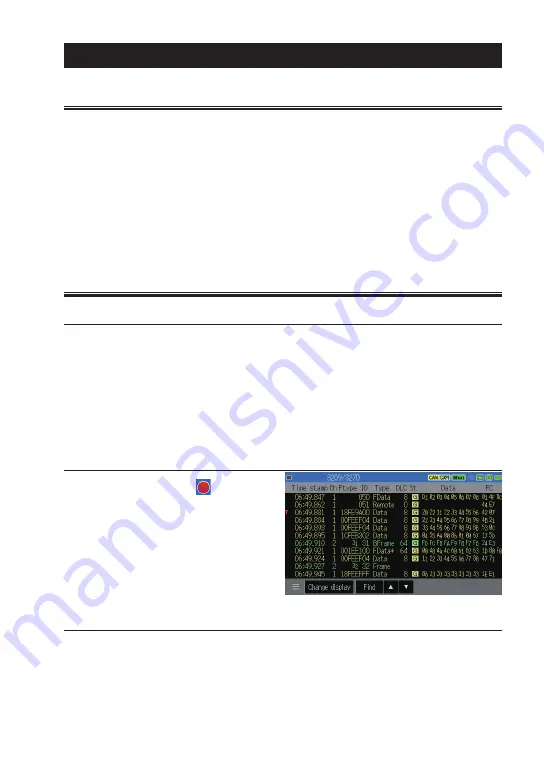


Start Monitoring 

Press [RUN] and“ 

  ”  will  be 

displayed on the upper left on the 

screen. Monitored data is displayed 

on the screen at real time and 

recorded in the capture buffer


Pause Display

Press [ESC] or touch ‟ Pause” , then the motion on the screen temporarily 

seems to be stopped while measurement is still continuing. While it stops 

renewing the display, ‟Pause‟ is displayed in green color. In order to cancel 

this, press [ESC] or touch ‟Pause” to go back to normal display.

-18-

Chapter 4 Monitor Function

4.1  Monitor Function

The monitor function records measured data in the capture buffer without 

impacting on a communication channel. Not only communication data but 

also the time stamp, external analog signal, signal status of external trigger 

are recorded. Trigger function helps finding data at specific conditions. And, 

retrieval function and scrolling display helps analyzing efficiently in the vast 

array of data in the capture buffer.

Содержание OP-SB7XL

Страница 1: ...Instruction Manual OP SB7XL Option for LE 3500XR LE 2500XR CAN FD CAN LIN Communications Expansion Kit The 3rd Edition 2022 02...

Страница 2: ......

Страница 3: ...e LINEEYE shall not be liable for direct in direct special incidental or consequential damages resulting from any defect in the product The warranty and remedies set forth above are exclusive and in l...

Страница 4: ...irst This Safety Information includes the following important information in order to not only have you learn the right way to use the analyzer but also prevent you from causing damage to people and p...

Страница 5: ...on appears Not flat or shaking place Place with leaking water or electricity Place affected by direct sun or near the fire Please do not leave the analyzer in the car during the summer Do not use at t...

Страница 6: ...9 2 3 Operation 11 2 4 Line State LED 12 Chapter 3 Basic Configuration 13 3 1 Top Menu 13 3 2 Interface and Operation Mode 14 3 3 Communication Conditions 14 3 4 Record control and J1939 16 Chapter 4...

Страница 7: ...8 Save and Load the Data 41 8 1 File Management Function 41 8 2 Save 41 8 3 Filter Function 42 8 4 Load 43 8 5 Delete 43 Chapter 9 Documents 44 9 1 Specifications of Function and Hardware 44 9 2 Sign...

Страница 8: ...e Operating Procedure Represent keys and items of the screen are enclosed in e g Press key Press MENU Successive key operations are represented by putting their symbols one after another e g Press MEN...

Страница 9: ...nce You have received all the standard accessories listed below Interface board 1 DB9 Monitor cable LE 009M2 2 3 line Probe cable LE 3LP 2 8 line Probe cable LE 8EX 1 Instruction manual This book 1 Cu...

Страница 10: ...ing communication system inspection and communication trouble shooting Function On line Monitor Function Monitor transmission reception data at real time and analyzes protocol and communication errors...

Страница 11: ...xpansion board OP SB7XC into the slot completely 5 Screw it on using M3 screws When the analyzer is turned on the power pre installed firmware OP SB7XL is started Please check the latest firmware from...

Страница 12: ...or LIN attached to the product Online Monitor It is able to measure 2 channels simultaneously Select CAN1 CAN FD CAN or LIN1 and CAN2 CAN FD CAN or LIN2 Simulation Select 1 port from CAN1 CAN2 LIN1 a...

Страница 13: ...obe cable Supply Vbat from external device analyzer does not supply External and trigger I O The analyzer has the external I O terminals besides the interfaces of CAN CAN FD and LIN They are for analo...

Страница 14: ...ected settings 0 F Enter numerical values Select send data TOP DEL Jump to the top of data Delete the entry indicated by the cursor END X Jump to the end of the screen Enter the data of Don t Care SHI...

Страница 15: ...ut 1 0V or less OFF ST2 IN4 About 2 0Vor more Red lighting About 1 0V or less OFF Shortcut keys By pressing 0 to E after MENU you can move to the frequently used setting screen Shortcut key Setting di...

Страница 16: ...tions of Ch2 Trigger Set the trigger factor and action Set the timer counter for trigger Record control Set the capture buffer recording type of external input and auto save Wave monitor Set the sampl...

Страница 17: ...ode Select an operation mode from Monitor or Simulation Simulation Ch Select a port for simulation from Ch1 or Ch2 Touch Simulation settings on the right bottom of screen for advanced settings It is a...

Страница 18: ...point Set the bit sample point between 60 90 On the right side of inputted sample point the actual sample point is displayed For CAN FD set Sample point data as well CRC type For CAN FD select ISO CR...

Страница 19: ...terval for external input and J1939 Time stamp Select a unit of time stamp from H M S M S 1ms 100us 10us and 1us The unit of 100us 10us and 1us are the elapsed time from start of the measurement Frame...

Страница 20: ...GN in decimal SPN SPN Suspect Parameter Number Input SPN in decimal Src Input source address in decimal Touch Change display for some t i me s t o ch a nge t o J1939display Only latest data will be tr...

Страница 21: ...een temporarily seems to be stopped while measurement is still continuing While it stops renewing the display Pause is displayed in green color In order to cancel this press ESC or touch Pause to go b...

Страница 22: ...USB bus power 10 Setting items 11 Change display mode Measured data Analog data of external input J1939 parameter 2 Wave monitor 2 12 Pause display available while it is measuring Search data availabl...

Страница 23: ...a in green and external input data in white If the data field of CAN FD CXPI contains more than 8byte it will display the rest of data in the following line Display Description Time stamp Display the...

Страница 24: ...frame A ACK error of CAN CAN FD F Form error for CAN CAN FD Framing error for LIN C CRC error of CAN CAN FD Checksum error of LIN E Error frame of CAN CAN FD B Break field error for LIN dominant is 1...

Страница 25: ...number using 0 9 keys and touch To Specified to see the specified data Mark Jump It is able to mark 5 positions of data and jump to the positions It is able to display marked position directly Place t...

Страница 26: ...s error CAN data 2 3 Retrieve specific CAN CAN FD frame CAN remote 2 Retrieve specific CAN remote frame LIN data 2 3 Retrieve specific LIN frame Time stamp 2 Retrieve data of specified time Ext IN 2 R...

Страница 27: ...backward older data starting from the top of data displayed on the screen Retrieve forward newer data starting from the top of data displayed on the screen Matched data is displayed on the top of scre...

Страница 28: ...ata on that table Frame type For CAN select from Data Standard Data Extended Re mot e St a nd a r d or Remote Extended For CAN FD select from FD Standard or FD Extended Chapter 5 Simulation Function 5...

Страница 29: ...to 8 Repeat Set the number of times of sending frames Set 0 to send repeatedly Interval Set the interval of sending frames between 1 99999ms There is an error of about 2 ms Data sweep Mark on the box...

Страница 30: ...time than frame length Schedule Mark on the box to send effective ID in the request ID from smaller table number table0 automatically Also it is possible to send the effective ID manually by pressing...

Страница 31: ...sponse ID in HEX Enable Mark on the box to send the response data automatically when the received ID is matched Data Touch the data field and data inputting window will be appeared Check sum Set the c...

Страница 32: ...ta are the one set on Data field Sweep value On the first box input the initial value in decimal On the second box input first target value and time ms On the third box input the second target value a...

Страница 33: ...Register 01 02 03 in the request ID Set ID 01 ID 03 in the response data table Analyzer sends header of ID 01 ID 02 ID 03 Analyzer sends response for ID 01 and ID 03 Analyzer receives response for ID...

Страница 34: ...same ID is set in the different table it transmits from smaller table number when the request ID is matched And it transmits bigger table number next time when the request ID is received Wake up signa...

Страница 35: ...it will keep L level for about 1ms after the last trigger factor is satisfied Chapter 6 Trigger Function 6 1 Trigger Function The trigger function is a function that triggers a special measurement pr...

Страница 36: ...4 Timer Counter Function Trigger Factor Select the trigger factors Error Select the error type from ACK error CAN CAN FD parity error LIN framing error stop bit is dominant Sync error or CRC error CA...

Страница 37: ...lect the timer or counter Set the setting of timer counter in advance 6 4 Timer Counter Function External input Select the logical status of external signal from 1 H 0 L X don t care All signals are A...

Страница 38: ...nt offset after the point offset for the specified amount set value x 32 bytes to the storage device as a TGSAVEnn DT file 1 While it saves data the next saving operation is ignored If the measurement...

Страница 39: ...clear 0 Trigger control Select the trigger control from disable enable or change reverse enable and disable Transmit CAN frame Transmi t speci f i ed tabl e after the selected response time 0 99999ms...

Страница 40: ...r factor 4 If the current value overflows it continues counting from 0 5 When the measurement stops the timer also stops at the point Action of counter0 1 1 The counter is cleared to 0 at the start of...

Страница 41: ...Set each timer counter with comparison values with 1 999999 Select the resolution of timer from 100ms 10ms or 1ms Timer Counter Display After the measurement touch on the left bottom of screen and se...

Страница 42: ...or sampling memory 2K sampling Select which part of the waveform measurement data before or after the trigger is prioritized Before Capture a lot of data before the trigger point some after the trigge...

Страница 43: ...n and display waveform Touch scale up button or pinch out the screen to expand the screen Swipe the screen to scroll the data Time between two points C M displays the time between the cursor and marke...

Страница 44: ...File operation from top menu 8 2 Save To save measured data touch Save data on the bottom of file operation screen To save setting condition touch Save setup on the bottom of file operation screen Na...

Страница 45: ...DT nn 00 99 Mark on Minimum time stamp to look for the files with time stamp after the selected time Mark on Maximum time stamp to look for the file with time stamp before the selected time Touch Appl...

Страница 46: ...8 4 Load file It is able to load DT and SU files Select the target file from file operation screen and touch Open When the selected file is loaded measured data is overwritten on the capture memory C...

Страница 47: ...resolution Hour minute second minute second 1ms 100 s 10 s 1 s 100 s 10 s 1 s is elapsed measurement time max 134 217 727 Simulation function Transmit pre registered test frames by key operation Incr...

Страница 48: ...nd 4 No use 5 FG Frame ground 6 No use 7 CAN I I O CAN CAN FD bus powe 8 No use 9 PWR I I CAN CAN FD bus powe 2 1 I indicates input to analyzer O indicates output from analyzer 2 LED of BAT1 lights wh...

Страница 49: ...er input is 0 5V to 6 0V 9 3 About J1939 PGN and SPN of J1939 71 Rev 2003 12 which LINEEYE analyzer translates are below PGN Display 61442 Electronic Transmission Controller 1 61443 Electronic Engine...

Страница 50: ...6 84 Wheel Based Vehicle Speed km h 65265 91 Accelerator Pedal Position 1 61443 92 Percent Load At Current Speed 61443 94 Fuel Delivery Pressure Pa 65263 96 Fuel Level 65276 98 Engine Oil Level 65263...

Страница 51: ...Distance km 65248 245 Total Vehicle Distance km 65248 246 Total Vehicle Hours hr 65255 247 Total Engine Hours hr 65253 250 Total Fuel Used L 65257 441 Auxiliary Temperature 1 deg C 65164 512 Driver s...

Страница 52: ...uch as the battery and software are free of charge from any defects in material and workmanship only when the products are operated in accordance with procedures described in the documents supplied by...

Страница 53: ...epair during warranty period LINEEYE repairs following the repair instruction Please provide the details of malfunction Repair after warranty period LINEEYE will repair the products at our own expense...

Страница 54: ...51...

Страница 55: ...52...

Страница 56: ...x 81 75 693 0163 URL https www lineeye com Email info lineeye co jp Printed in Japan LINEEYE CO LTD M 32XLE LE There is a registration page on our web site https www lineeye com Please register your p...

Отзывы: