©2013 2GIG Technologies Inc. All Rights Reserved.
1
Telguard Cellular Service
INSTALL INSTRUCTIONS
These instr
ucions
are wri
t
en f
o
r use when installing a 3G Cell Ra
dio
Module
int
o
a 2GIG C
o
ntr
o
l Panel that will be using the Telguard
Cellular Service.
The 3G Cell Radi
o
Module
is a snap-in cell radi
o
that pr
o
vides 2-way-
v
o
ice t
o
a Central Sta
io
n, transmits security inf
o
r
maio
n t
o
on
line
portals,
and delivers the latest Over-The-Air
fi
rmware updates t
o
the
2GIG C
o
ntr
o
l Panel using the Telguard Cellular Service.
Contents
•
3G Cell Ra
dio
M
o
dule
•
TelGuard SIM Card
•
2 screws
•
2
lock
washers
•
Install Instruc
ions
(Step 1) Register Telguard
Cellular Service
T
o
aci
vate the 3G Cell Ra
dio
M
o
dule, Telguard requires that the
module
be registered.
(Step 2) Install the 3G Cell Radio Module
The 2GIG-GC 3G Cell Radi
o
Module
is a snap-in cell radi
o
that
pr
ovid
es 2-way-v
o
ice t
o
a Central
Sta
io
n, transmits security
inf
o
rma
io
n t
o
o
nline
po
rtals, and
delivers the latest Over-The-Air
fi
rmware updates t
o
the 2GIG
Cont
r
o
l Panel. The 2GIG-GC 3G
Cell Ra
dio
Module
must be
installed with the 2GIG-ANT3X
Antenna.
IMPORTANT:
The C
o
ntr
o
l Panel
Firmware must be vers
io
n
1.10.1
o
r higher f
o
r the 3G
Cell Ra
dio
Module
t
o
w
o
r
k
.
The (2GIG-ANT3X) antenna is
required f
o
r use with the 3G
Cell Ra
dio
M
odul
e.
Bef
o
re installing the 2GIG-GC 3G
Cell Ra
dio
Mo
dule ma
k
e sure that
both
the AC
po
wer and the
ba
t
ery are
disconnect
ed fr
o
m
the 2GIG
Cont
r
o
l Panel:
1
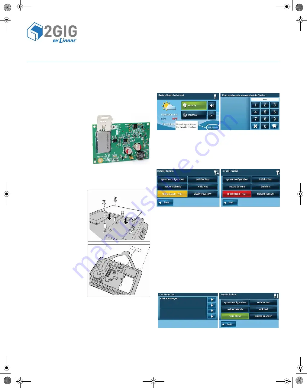
Plug the Cell Ra
dio
Module
int
o
the C
o
ntr
o
l Panel.
2
Secure the Cell Ra
dio
Module
with 2 screws and l
o
c
k
washers.
3
Co
nnect the ANT3X Antenna t
o
the m
o
dule.
4
Thread the Antenna thr
o
ugh the bac
k
o
f the
Cont
r
o
l Panel.
5
Cl
o
se the
Cont
r
o
l Panel and secure it.
WARNING:
As with all electrical appliances, a
shock
hazard exists
if any electrical current is
connec
ted t
o
the 2GIG C
o
ntr
o
l Panel
by AC
po
wer
o
r ba
t
ery while
inserin
g, rem
o
ving
o
r replacing
parts.
(Step 3) Test the Cell Signal Strength
1
P
o
wer up the C
o
ntr
o
l Panel.
2
T
o
access the
Installer Toolbox Screen
, press the l
o
g
o
in the
boto
m c
o
rner.
3
Enter y
o
ur 4-digit Installer C
o
de.
4
Fr
o
m the
Installer Toolbox Screen
, press the
Radio Status
bu
to
n.
5
Verify that the signal strength meets the rec
o
mmended minimum
o
f 7/31. If the
Radio Status
bu
to
n is
green
, the radi
o
is c
o
nnected
with g
oo
d signal strength.
If the
Radio Status
bu
to
n is yel
lo
w, the
connecion
status is in idle
state.
If the
Radio Status
Bu
to
n is red, then
no
co
nnec
io
n exists.
(Step 4) Verify the Service Status
A
t
er pressing the
Radio Status
bu
to
n, l
ook
f
o
r
Service Status
. It
shou
ld say “pending...”
(Step 5) Activate and Transmit Panel Alarms (Using the
Cellular Radio Network)
1
If a POTS
module
has been installed and a
phone
line is
at
ached t
o
the
Cont
r
o
l Panel, unplug the telc
o
line. A
Phone
Line Failure Alert
shou
ld appear.
2
T
o
aci
vate the Cell Radi
o
M
odul
e, press Cell
Phone
Test
o
n the
Ra
dio
Mode
m Status screen.
3
While the cell
phone
test
occu
rs, a status message appears.
4
If the cell
phone
test passes (thus ac
i
va
ing
the cell radi
o
modul
e)
the
Radio Status
bu
to
n
o
n the
Installer Toolbox Screen
appears
green and
registered
o
n the
Radio Status Screen
.
5
It may ta
k
e several sec
o
nds f
o
r the
aci
va
ion
inf
o
rma
io
n t
o
pr
o
pagate bac
k
t
o
the C
o
ntr
o
l Panel and update the service status
t
o
registered
.
NOTE:
Once
aci
vated
all
remaining signals will be sent t
o
the
Central Sta
ion.
INSTRUC
TIONS, INST
ALL 2GIG-GC3G
A-T P/N 77-000008-001 REV
A -
INK BLA
CK - MA
TERIAL: 20 LB MEAD BOND - SIZE 8.5000” X 11.000” SC
ALE 1 - 1 PRINTING: FRONT AND BA
CK - F
OLD


