Linde BOC Smootharc Advance II MIG 400R Скачать руководство пользователя страница 17

Electrode angle

The angle which the electrode makes with the work is important to 

ensure a smooth, even transfer of metal. The recommended angles  

for use in the various welding positions are covered later. 

Correct travel speed

The electrode should be moved along in the direction of the joint being 

welded at a speed that will give the size of run required. At the same 

time the electrode is fed downwards to keep the correct arc length 

at all times. As a guide for general applications the table below gives 

recommended run lengths for the downhand position.
Correct travel speed for normal welding applications varies between 

approximately 125–375 mm per minute, depending on electrode size, 

size of run required and the amperage used.
Excessive travel speeds lead to poor fusion, lack of penetration, etc. 

Whilst too slow a rate of travel will frequently lead to arc instability, slag 

inclusions and poor mechanical properties.

Run length per electrode – BOC Smootharc 13

Electrode 

Size (mm)

Electrode 

Length (mm)

Run Length (mm)
Minimum

Maximum

4.0

350

175

300

3.2

350

125

225

2.5

350

100

225

Correct work preparation 

The method of preparation of components to be welded will depend on 

equipment available and relative costs. Methods may include sawing, 

punching, shearing, lathe cut-offs, flame cutting and others. In all 

cases edges should be prepared for the joints that suit the application. 

The following section describes the various joint types and areas 

of application. 

3.5  Types of joints 

Butt welds 

A butt weld is a weld made between two plates so as to give continuity 

of section. Close attention must be paid to detail in a butt weld to ensure 

that the maximum strength of the weld is developed. Failure to properly 

prepare the edges may lead to the production of faulty welds, as correct 

manipulation of the electrode is impeded. 
Two terms relating to the preparation of butt welds require explanation 

at this stage. They are: 


 Root Face:  the proportion of the prepared edge  

that has not been bevelled. 


 Root Gap:  the separation between root  

faces of the parts to be joined. 

Various types of butt welds are in common use and their suitability for 

different thickness of steel are described as follows: 

Square Butt Weld

Weld Beads

Weld Beads

Layers

Layers

70˚ - 85˚

Electrode

Slag

Weld Pool

Weld Metal

Arc

Direction Of Welding

The edges are not prepared but  

are separated slightly to allow fusion through the full thickness  

of the steel. Suitable for plate up  

to 6 mm in thickness. 

Single ‘V’ Butt Weld

Weld Beads

Weld Beads

Layers

Layers

70˚ - 85˚

Electrode

Slag

Weld Pool

Weld Metal

Arc

Direction Of Welding

This is commonly used for plate up to 16 mm in thickness and on 

metal of greater thickness where access  

is available from only one side. 

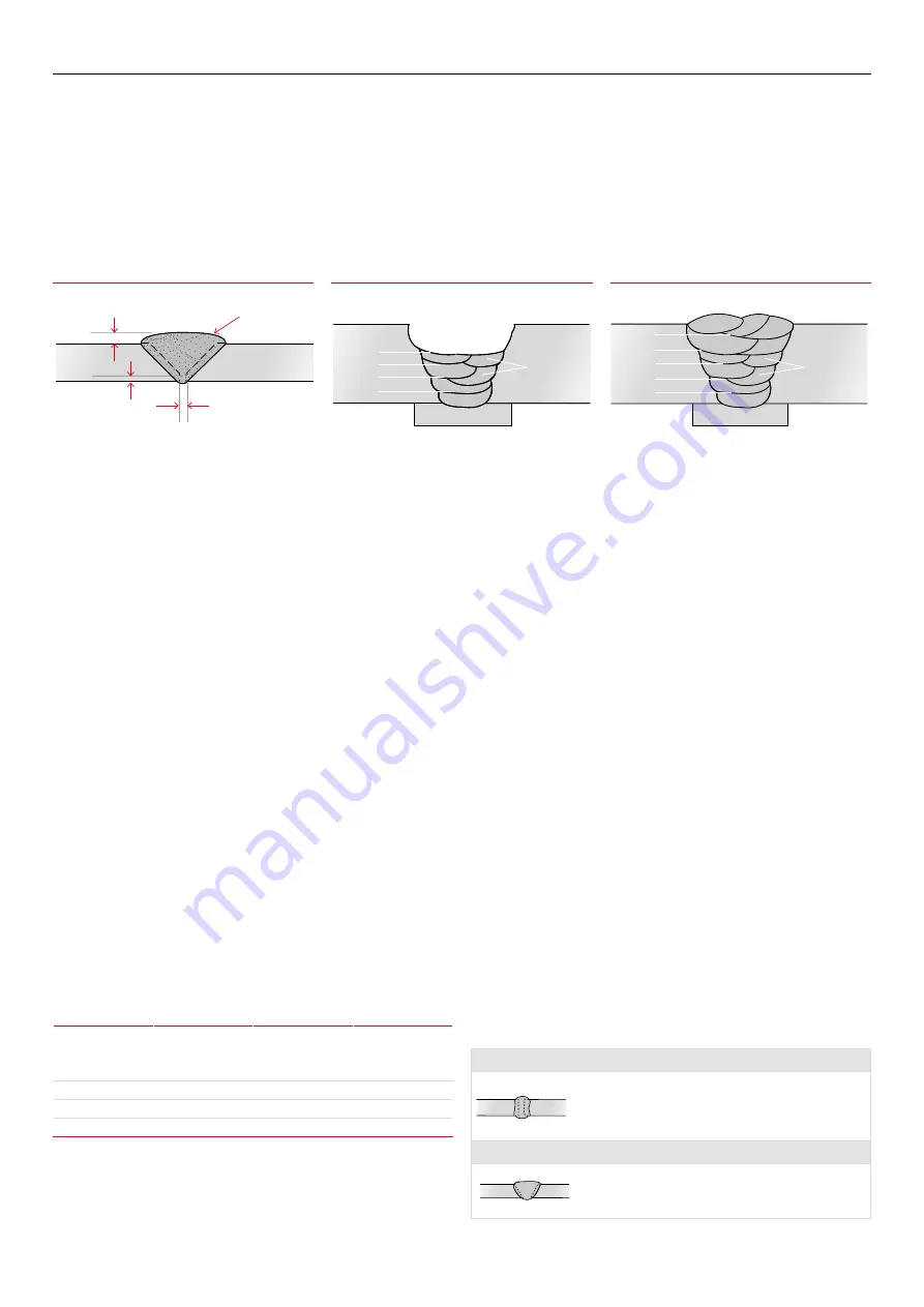
Electrode Angle for 1st and 2nd Layers

Electrode Angle for Subsequent Layers

Butt Welding

Weld Face

Face Reinforcement

Root Face

Root Gap

Weld Beads

Weld Beads

Layers

Layers

70˚ - 85˚

Electrode

Slag

Weld Pool

Weld Metal

Arc

Direction Of Welding

Weld Beads

Weld Beads

Layers

Layers

70˚ - 85˚

Electrode

Slag

Weld Pool

Weld Metal

Arc

Direction Of Welding

17

BOC Smootharc Advance II MIG 400R Operating manual

Содержание BOC Smootharc Advance II MIG 400R

Страница 1: ...MIG 400R Operating manual 6PRRWKDUF GYDQFH GYDQFH...

Страница 2: ...he document has been issued Neither BOC nor any of its agents has independently verified the accuracy of the information contained in this document The information in this document is commercial in co...

Страница 3: ...nique 21 4 0 General Welding Information 23 4 1 Recommended Welding Parameters 23 5 0 Correct Application Techniques 25 6 0 Package contents 27 7 0 Installation 28 7 1 Installation for MIG MAG process...

Страница 4: ...imary terminals and live parts effectively covered Never strike an arc on any gas cylinder Never use oxygen for venting containers Diagram and safety explanation Electrical safety alert Welding electr...

Страница 5: ...ys have enough ventilation in confined spaces Be alert to this at all times Keep your head out of the fumes rising from the arc Fumes from the welding of some metals could have an adverse effect on yo...

Страница 6: ...sonnel approved by BOC should perform repairs Always disconnect mains power before investigating equipment malfunctions Parts that are broken damaged missing or worn should be replaced immediately Equ...

Страница 7: ...res with oxygen or helium mixtures Each gas or gas mixture has specific advantages and limitations Other forms of MIG welding include using a flux cored continuous electrode and carbon dioxide shieldi...

Страница 8: ...heir higher deposition rates than solid MIG wires What is often not explained is how they deliver these higher values and whether these can be utilised For example if a solid MIG wire is used at 250 a...

Страница 9: ...ates 2 3 Introduction to Metal Cored Arc Welding MCAW How it Works Metal cored arc welding MCAW uses the heat generated by a DC electric arc to fuse metal in the joint area the arc being struck betwee...

Страница 10: ...r in FCAW are Dip transfer Globular transfer Spray transfer Pulsed arc transfer operation has been applied to flux cored wires but as yet is not widely used because the other transfer modes are giving...

Страница 11: ...ecause of its low density and high thermal conductivity spray transfer in position can be carried out The current flows continuously because of the high voltage maintaining a long arc and short circui...

Страница 12: ...ire Material BOC MIG Wire AS2074 C1 C2 C3 C4 1 C4 2 C5 C6 BOC Mild Steel MIG Wire BS3100 AW1 A2 A3 BOC Mild Steel MIG Wire BS1504 430 480 540 BOC Mild Steel MIG Wire ASTM A36 A106 EN8 8A BOC Mild Stee...

Страница 13: ...ome grades of self shielded flux cored wires i e E71T 11 E71T GS etc needs to be welded on electrode negative Work return lead fitted to the positive connector Selection of the correct shielding gas T...

Страница 14: ...Australia is 50 Hz Hertz 3 2 Welding machine The most important consideration when contemplating the use of arc welding for the first time is the purchase of a suitable welding machine BOC supplies a...

Страница 15: ...positions using AC or DC power sources Its easy striking characteristics and the tolerance it has for work where fit up and plate surfaces are not considered good make it the most attractive electrod...

Страница 16: ...the current in the middle of the range specified on the electrode package is considered to be the optimum In the case of welding machines with separate terminals for different size electrodes ensure t...

Страница 17: ...should be prepared for the joints that suit the application The following section describes the various joint types and areas of application 3 5 Types of joints Butt welds A butt weld is a weld made b...

Страница 18: ...60 This preparation provides a ledge on the lower member which tends to retain the molten metal General notes on Butt Welds The first run in a prepared butt weld should be deposited with an electrode...

Страница 19: ...mbers are fitted as shown leaving a V shaped groove in which a fillet weld is deposited Fusion should be complete for the full thickness of the metal In practice it is generally necessary to have a ga...

Страница 20: ...ally result in collapse of the metal at the vertical plate and serious undercutting For large leg lengths multiple run fillets are necessary These are built up as shown The angle of the electrode for...

Страница 21: ...lectrode coating moisture contents Defects caused by welding technique Slag Inclusions Slag inclusions occur when slag particles are trapped inside the weld metal which produces a weaker weld These ca...

Страница 22: ...defect can be excessive travel speed electrode size too large welding current too low poor joint preparation letting the weld metal get ahead of the arc Lack of fusion can usually be prevented by redu...

Страница 23: ...Wire feed speed m min 3 5 5 0 4 0 7 0 4 0 7 0 4 0 7 0 7 5 9 0 9 0 12 0 8 0 10 0 7 0 9 0 Gas rate flow L min 15 15 15 15 15 15 18 18 Travel speed mm min 350 500 350 500 320 500 280 450 800 1000 420 50...

Страница 24: ...eter mm 1 2 1 2 1 6 1 2 1 2 1 6 1 6 Current amps 200 250 300 350 300 400 200 250 175 200 350 400 200 250 Voltage volts 27 29 31 34 30 32 25 28 24 25 29 32 24 26 Wire feed speed m min 6 9 10 0 13 2 16...

Страница 25: ...cement 10 Torch positioned at a drag angle of 10 narrow bead with excessive reinforcement Flux cored welding with cored wires takes place normally with the drag technique The welding torch is tilted a...

Страница 26: ...rease in temperature has a positive influence in the melt off rate of the wire that will have an influence on the weldbead profile Influence of the change in electrical stickout length on the weldbead...

Страница 27: ...455 BOC Argon regulator Work return lead Electrode holder Wire feeder 1 5m 10m inter connecting cable 1 5m 10m inter connecting cable Wire feed rollers Knurled 0 8 0 9 1 0 1 2 1 2 1 6 U Groove 0 8 0...

Страница 28: ...ol into the socket at the rear of the power source Fit the wire feed power cable into the front of the machine Attach the earth cable to the rear of the machine Primary current rating This machines ha...

Страница 29: ...ar of the power source Repeat this on the wire feeder For select flux cored wire and self shielded wire DCEN Connect the inter connection cable wire feed control into the socket at the rear of the pow...

Страница 30: ...se tightly 2 Connect the work return lead into the negative 12 of the machine and fasten it clockwise 3 Please note that for manual metal arc MMA welding the electrode holder can be switched to the ne...

Страница 31: ...f all functionalities 8 2 MMA Welding Setup 1 Ensure the machine is correctly plugged into the main circuit 2 Proper PPE must be worn 3 Ensure workplace safety such as fume extraction is in place 4 Fi...

Страница 32: ...re to be feed through without the shielding Voltage adjustment The inverter power source allows infinite adjustment of welding voltage even when the arc is struck Wire speed amperage The wire feed con...

Страница 33: ...fects reduced spatter heat control has no effect when spray arc welding because there is no more change in current the inductance coil plays no further part A certain amount of inductance with spray t...

Страница 34: ...Welding torch overheats Welding torch underrated for welding application Liners Erratic wire feed wire snarls up at outlet guide Liner of incorrect type and size for wire in use worn or dirty liner li...

Страница 35: ...KNROL0809 Knurled 1 0 1 2 ADVANCEKNROL1012 Knurled 1 2 1 6 ADVANCEKNROL1216 Aluminium U Groove 0 8 0 9 ADVANCEUROL0809 U Groove 1 0 1 2 ADVANCEUROL1012 U Groove 1 2 1 6 ADVANCEUROL1216 Steel Stainless...

Страница 36: ...machine and its consumables 12 1 Power Source Check electrical connections of unit at least twice a year Clean oxidised connections and tighten Inner parts of machine should be cleaned with a vacuum c...

Страница 37: ...00A 50 400A Output Voltage 16 5 34V 22 36V Duty cycle 40 400A 45 400A 60 346A 325A Power factor 0 93 Efficiency 85 Wire feeder Remote Wire speed 2 16 m min Wire spool diameter 270mm Wire diameter 0 8...

Страница 38: ...d to daily allowances or accommodation and travelling costs NOTE Under the terms of warranty welding torches and their consumables feed drive rollers and feeder guide tubes are not covered Direct or i...

Страница 39: ...39 BOC Smootharc Advance II MIG 400R Operating manual...

Страница 40: ...of printing Whilst proper care has been taken in the preparation no liability for injury or damage resulting from its improper use can be accepted For more information contact the BOC Customer Engage...

Отзывы: