


FineLine 300HD Plasma System
BK8053-000107 Rev A.01
This information is subject to the controls of the Export Administration Regulations [EAR]. This information shall not be provided to
non-U.S. persons or transferred by any means to any location outside the United States contrary to the requirements of the EAR.
Page 36 of 118
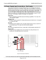
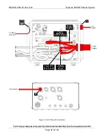
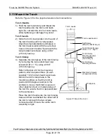
3.8 Automatic Gas Console Input Connections
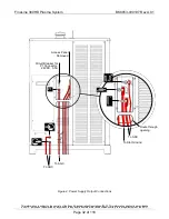
Refer to Figure 7 for the physical location of all connections.
Make connections in
the order shown below.
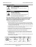
When making brass fitting connections, use two opposing
wrenches and only tighten enough to make gas seals. The fittings are subject to
damage if over tightened.
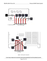
Plasma Pre / Post Gas Hose
1) Connect the plasma pre / post hose to the fitting on the input side of
the AGC labelled with the symbol shown and to the corresponding
fitting on the Power Supply.
Plasma Marking Gas Hose
2) Connect the plasma marking hose to the fitting on the input side of the
AGC labelled with the symbol shown and to the corresponding fitting
on the Power Supply.
Shield Marking Gas Hose
3) Connect the shield marking hose to the fitting on the input side of the
AGC labelled with the symbol shown and to the corresponding fitting
on the Power Supply.
Shield Cutting Gas Hose
4) Connect the shield cutting hose to the fitting on the input side of the
AGC labelled with the symbol shown and to the corresponding fitting
on the Power Supply.
Plasma Cutting Gas Hose
5) Connect the plasma cutting gas hose to the fitting on the input side of
the AGC supply labelled with the symbol shown and to the
corresponding fitting on the Power Supply.
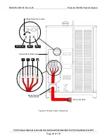
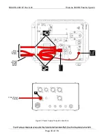
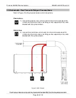
Automatic Gas Console Ground Cable
6) Connect the AGC ground cable (user-supplied) to the ground stud on
the AGC labelled with the symbol shown and to the star ground point
for the cutting system. Make sure that good metal-to-metal contact is
made.