


FineLine 300HD Plasma System
BK8053-000107 Rev A.01
This information is subject to the controls of the Export Administration Regulations [EAR]. This information shall not be provided to
non-U.S. persons or transferred by any means to any location outside the United States contrary to the requirements of the EAR.
Page 34 of 118
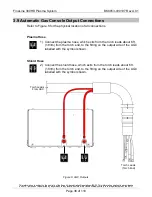
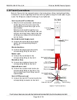
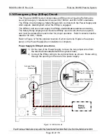
3.7 Arc Start Console Output Connections
Refer to Figure 6 for the physical location of all connections. Secure the cover on the
ASC when installation is complete. When making brass fitting connections, use two
opposing wrenches and only tighten enough to make water or gas seals. The fittings
are subject to damage if over tightened.
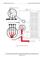
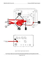
Torch Leads
1) Remove the threaded ring from the brass shield connector on the end
of the torch leads. Route the torch leads through the opening in the
ASC. Push the brass shield connector through the hole until it is
seated against the ASC enclosure.
2) Slide the threaded ring over the torch leads, thread it onto the brass
shield connector, and then tighten firmly. The shield connector will
ground the braided shield to the ASC enclosure in order to help reduce
high frequency noise emission. Using an ohmmeter, measure for zero
ohms between the braided shield and the ground stud located on the
outside of the ASC enclosure.
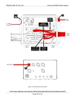
3) Connect the torch CTP (Clear The Plate, a.k.a. Ohmic Sense) sensor
lead to the red hexagonal standoff.
4) Connect the torch electrode/coolant supply lead to the brass cathode
manifold. The torch electrode/coolant supply lead has right hand
threads.
5) Connect the torch coolant return lead to the brass cathode manifold.
The torch coolant return lead has left hand threads.
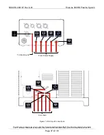
6) Connect the torch nozzle lead to the angled (“L”) bracket on the red
hexagonal standoff as shown using the supplied hardware. The torch
nozzle lead has right hand threads.
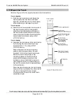
ASC Control Cable
7) Connect the ASC control cable to the connector labeled P2 on the
ASC and to the connector labeled P2 on the AGC.
The AGC supplies 24VDC to the ASC through this cable. The 24VDC
is protected by a PTC overcurrent protection device, which
automatically resets.
ASC Ground Cable
8) Connect the ASC ground cable (user-supplied) to the ground stud on
the ASC labelled with the symbol shown and to the star ground point
for the cutting system. Make sure that good metal-to-metal contact is
made.
P2