i
PS3268C
24-Port Web Smart GbE PoE+ Switch
QUICK INSTALLATION GUIDE
Страница 1: ...i PS3268C 24 Port Web Smart GbE PoE Switch QUICK INSTALLATION GUIDE ...
Страница 2: ...tch in a 19 inch Rack 4 Mounting the Switch on Desk or Shelf 5 Connecting the AC Power Cord 6 Installing SFP Modules 7 Connecting Console Port 7 Chapter 3 Managing Switch Using the Web Interface 8 Manage the Switch Using Web Browser 8 Chapter 4 Troubleshooting 9 Appendix A Technical Specifications 10 Hardware Specification 10 1000 MBPS Gigabit Ethernet Collision Domain 11 ...
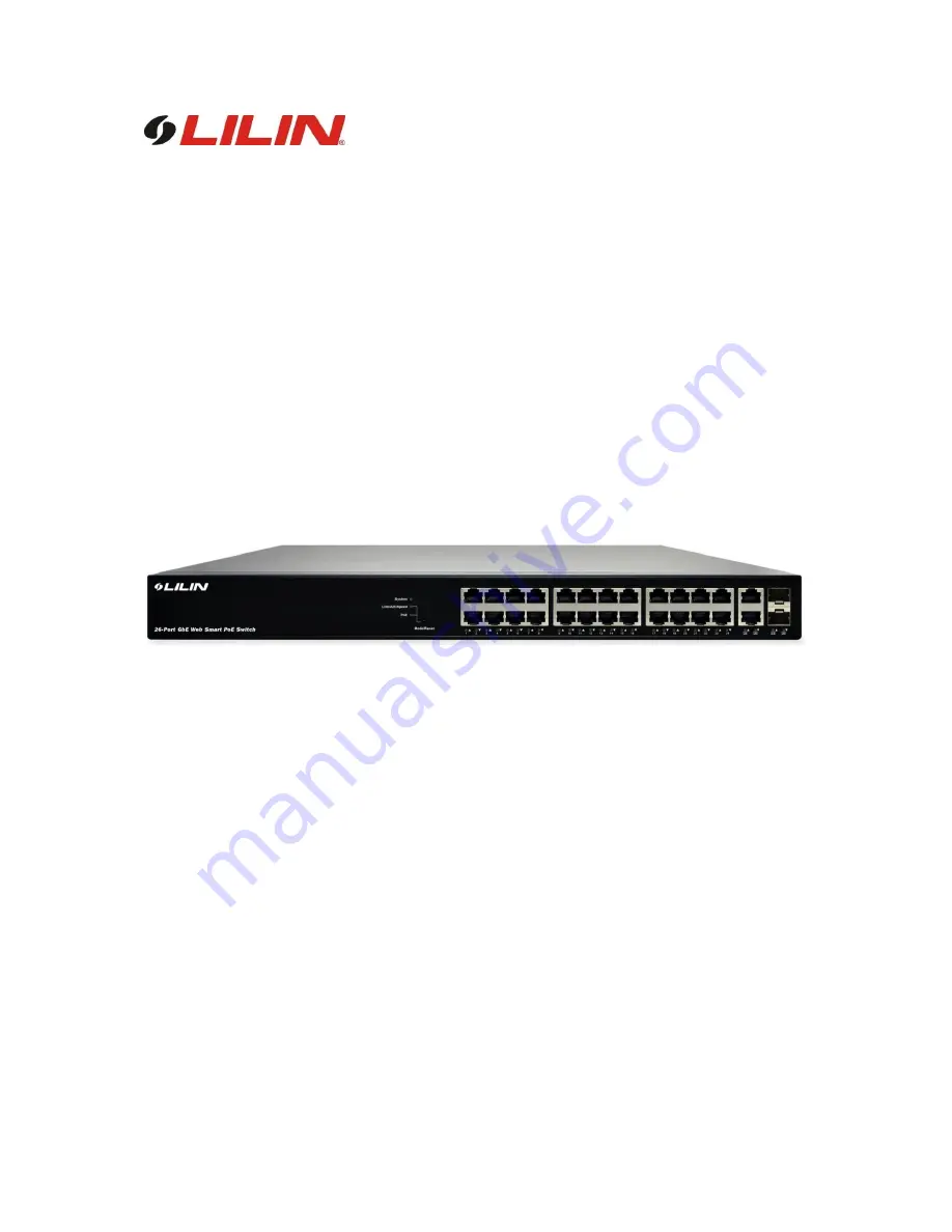
Страница 3: ...e describes hardware installation and basic troubleshooting for these managed switches Front panel of the Switch Figure 1 Front panel of the switch Table 1 Port Status LEDs LED Condition Status TP Link Act Speed Green Blink Lit Green when TP link on 1000Mbps Amber when TP link on 10 100Mbps TP PoE Green Off Lit Green when PoE link good SFP Link Act Speed Green Blink Lit Green when SFP link good Li...
Страница 4: ...e 3 Mode Status LED LED Condition Status Link ACT Speed Green Yellow OFF Green when the link on 1000Mbps Yellow when the link on 100Mbps Off when the link on 10Mbps PoE Green OFF Lit Green shows all LED of each port are in PoE Mode Rear panel of the Switch Figure 2 Rear panel of the switch AC Power Socket ...
Страница 5: ...ith cable then you need to install a surge arrester in between outdoor device and switch Figure 3 Add a surge arrester between outdoor device and switch NOTE The switch is an indoor device if it is to be used with outdoor devices such as outdoor IP camera or outdoor WiFi AP then users must install a surge arrester to protect the switch WARNING Self demolition on Product is strictly prohibited Dama...
Страница 6: ...ack Step1 Attach the mounting brackets to both sides of the chassis with screws Figure 4 Attaching mounting brackets to the switch Step2 Place the switch on a rack shelf in the rack Push the switch in until the oval holes in the brackets align with the mounting holes in the rack posts Step3 Attach the mounting brackets to the rack posts with screws Figure 5 Attaching mounting brackets to the rack ...
Страница 7: ...k or Shelf Step1 Verify that the workbench is sturdy and reliably grounded Step2 The rubber feet are included in the accessory kit Attach the four adhesive rubber feet to the bottom of the switch Figure 6 Attaching the Rubber Feet ...
Страница 8: ...er cord to the AC power receptacle Step1 Connect one end of the AC power cord to the AC power receptacle on the switch Step2 Connect the other end of the AC power cord to the AC power outlet Step3 Examine the power LED If it is ON the power connection is correct ...
Страница 9: ...mly to ensure that the module seats into the connector Figure 8 Installing a SFP Module into a SFP Module Slot Connecting Console Port Figure 9 Connecting Console Port Start a terminal application such as HyperTerminal on the computer Configure the utility with the following parameters Default Baud rate 115 200 bps Parity None Stop bit 1 Data bits 8 Flow control none The default username is admin ...
Страница 10: ...ter NOTE 1 If the switch is using the factory default IP address of 192 168 0 1 you must chose an IP address for the computer in the range of 192 168 0 1 192 168 0 253 that is not already in use 2 If the IP addresses is assigned by a DHCP server make sure the DHCP server is running and can be reached from the switch and the computer It might be necessary to disconnect and reconnect the devices for...
Страница 11: ...nnecting device Make sure that all cables used are correct and comply with Ethernet specifications Check for a defective adapter card cable or port by testing it in an alternate environment where all products are functioning Slow file transfer or there is performance degradation Half or full duplex setting on the switch and the connected device are not the same Make sure that the attached device i...
Страница 12: ...EEE802 3at PoE 30W Y IEEE802 3af PoE 15 4W Y UPoE 60W PoE Port 24 Available PoE Power 370W HW Performance Switching Bandwidth 52Gbps Forwarding Performance 38 7Mpps MAC Address 8K Jumbo Frames 9216 Bytes Environmental Specification Operating Temperature 0 C to 45 C Operating Humidity 10 to 90 RH Storage Temperature 20 to 70 C Storage Humidity 10 to 90 RH Mechanical Specification Dimensions H x W x...
Страница 13: ... LC 50 125 micron multimode fiber 400 MHz km 500 MHz km 500 m 1641 ft 550 m 1805 ft LC LC Table 7 Maximum 1000BASE LX LHX XD ZX Gigabit Fiber Cable Length Fiber Size Fiber Bandwidth Maximum Cable Length Connector 9 125 micron single mode fiber 1310nm N A 10km 6 2 miles LC 9 125 micron single mode fiber 1550nm N A 30km 18 64 miles 50km 31 06 miles LC LC Table 8 Maximum 1000BASE LX Single Fiber Giga...