5. Software Control - Lightware Device Controller
UMX-HDMI-140 series– User's Manual
60
Applied firmware package: v1.3.0b5 | LDC software: v2.5.6b2
Condition Triggering
DIFFERENCE:
This feature is
available only in UMX-HDMI-140-Plus
model from FW package v1.3.0b5.
This improvement works as if a
condition is detected. When a complex
control system is built, a Condition may
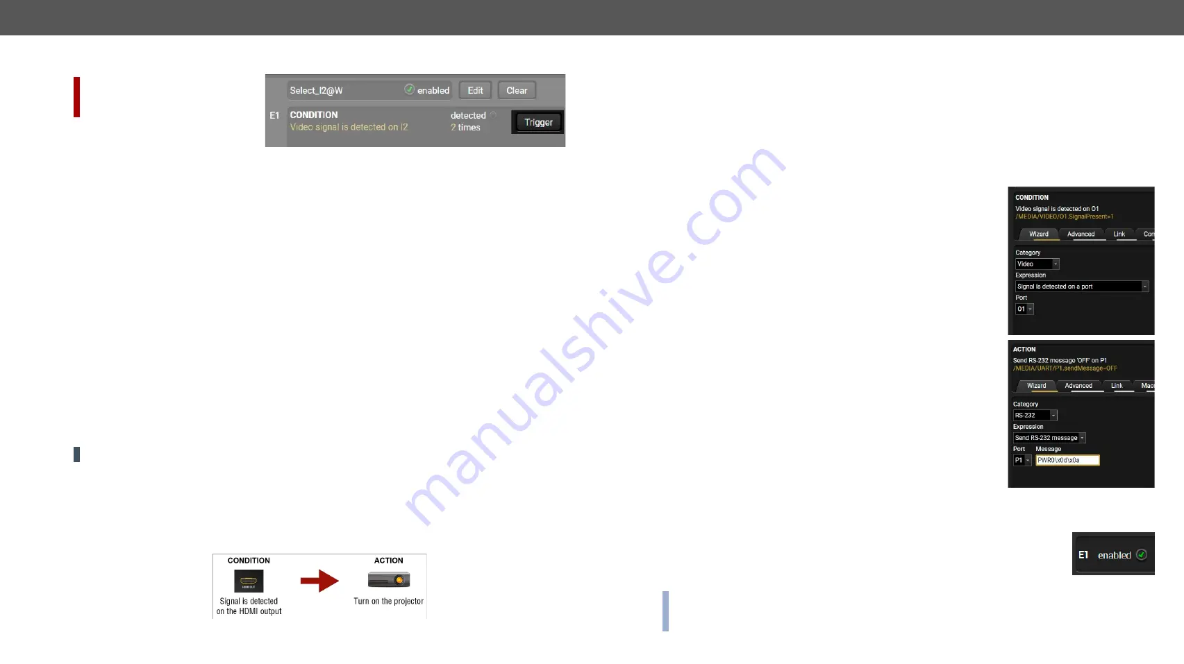
trigger numerous Actions. A typical example is when a system is powered on and the ’ready-to-use’ state
has to be loaded. In this case, there could be many actions which are based on the same condition. In order
to reduce the number of the commands, you can trigger one ’key’ condition, which could start the whole
process.
5.10.4.
Clear One or More Event(s)
Clear an Event
Press the
Clear
button in the Event list or in the header section in the Event editor.
Clear all Events
When all the Events must be cleared press the
Load factory defaults
button above the Event list. You will be
prompted to confirm the process.
5.10.5.
Export and Import Events
The feature allows saving all the Events. The backup file can be uploaded to another UMX-HDMI-140 switcher.
Export all the Events
Step 1.
Press the
Export
button above the Event list.
Step 2.
The Save as dialog box will appear. Set the desired folder and file name, then press the
Save
button.
The generated file is a simple text file which contains LW3 protocol commands. The file can be viewed by a
simple text editor, e.g. Notepad.
ATTENTION!
Editing the file is recommended only for expert users.
Import all the Events
Step 1.
Press the
Import
button above the Event list.
Step 2.
The Open dialog box will appear. Select the desired folder and file, then press the
Open
button.
5.10.6.
Event Creating - Example
The following example shows you on a real-life situation how to set up an Event.
The Concept
The UMX-HDMI-140-Plus switcher is connected to a projector by the HDMI output port. The switcher is also
connected to the projector by the RS-232 port and can send commands via the serial line. The task is to turn
on the projector when signal is detected on the HDMI output port.
RS-232 Settings
Make sure that the serial line is established between the switcher and the projector. Check that the RS-232
settings of the switcher is exactly the same as required for the projector: baud rate, data bits, parity, stop
bits. The switcher needs to be set to: Control protocol: LW3; and RS-232 mode: Pass-through. See the
relevant LDC settings in the
section.
Setting the Event
Step 1.
Set the condition.
Select the required parameters to set the condition:
▪
Category
: Video;
▪
Expression
: Signal is detected on a port;
▪
Port
: O1.
Click on the
Apply
button to complete the procedure, then the condition
appears on the upper side in textual and LW3 command format as well.
Step 2.
Set the action.
If the condition is fulfilled, the following action needs to be launched: the
receiver sends a command to the projector over the serial line:
▪
Power on
- the required command which is accepted by the projector:
PWR0<CR><LF>
E.g. the command has to be closed with the <CR><LF> characters so they
need to be escaped. You can use the following format for escaping:
<command
1
><\x0d\x0a><command
2
><\x0d\x0a>...
...<command
n
><\x0d\x0a>
In the current case the command is: PWR0\x0d\x0a
Select the required parameters to set the action:
▪
Category
: RS-232;
▪
Expression
: Send RS-232 message;
▪
Port
: P1;
▪
Message
: PWR0\x0d\x0a
Step 3.
Enable the Event.
Select the
E1 enabled
pipe in upper left corner to set the Event as launched.
INFO:
If you do not find the required category/expression/etc what you need, choose the Advanced mode
in the Wizard where the entire LW3 structure tree is available. For example instead of signal detection you
can set a specified resolution or color range either as a condition.


