5. Software Control - Lightware Device Controller
UMX-HDMI-140 series– User's Manual
57
Applied firmware package: v1.3.0b5 | LDC software: v2.5.6b2
5.10.
Event Manager
The feature means that the device can sense changes on its ports and able to react
according to the pre-defined settings. The development idea of the Event manager
is based on users’ feedbacks. In many cases internal events (such as signal present
or HDCP active) are necessary to display but it is not easy when the device is hard
to access (e.g. built under the desk). For more details and examples about Event Manager please visit our
website
https://lightware.com/support/guides-and-white-papers
) and download
Event Manager user's guide
in the Downloads section.
#eventmanager
The Event manager can be configured to perform an action if a condition has been detected. E.g. the desired
setup is that after a certain type of signal has been detected on I1 port, the port has to be switched to O1.
The settings can be done via the LDC in the main menu, or by LW3 protocol commands. Configurable events
number depends on the device what you are using actually.
Numerous new ideas and requests have been received in connection with the features and settings of the
Event manager since the first release. Therefore, the user interface has been re-designed and many new
functions implemented. The Event editor can be opened by pressing the
Edit
button at each Event.
There is a
grey bar
on the left of the Event panel in each line. If a condition and an action are set and the Event
is enabled, the bar is displayed
in green
.
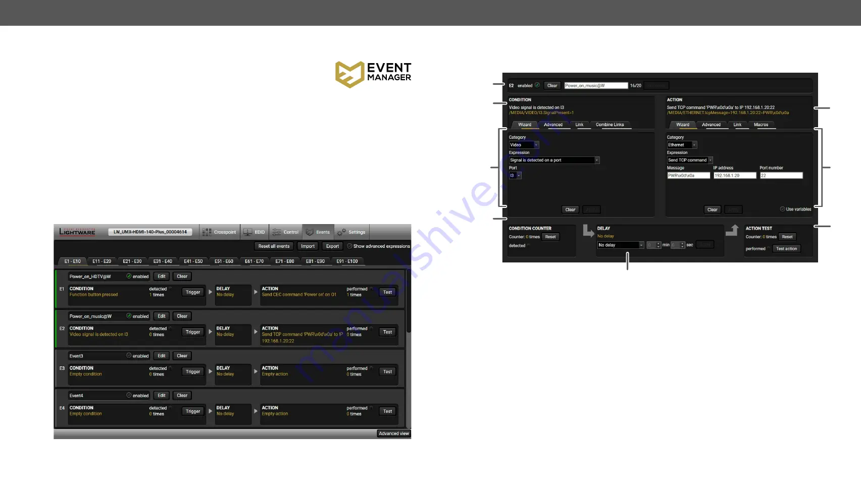
Control menu, Event Manager tab
5.10.1.
The Event Editor
Press the
Edit
button in the desired Event line to open the Event editor window.
1
Event header
The name of the Event is displayed. Type the desired name and press the Set
name button. The Event can be cleared by the Clear button. Use the tick mark
to enable/disable the Event.
2
Condition header
If the condition is set, the description (white colored text) and the exact LW3
protocol expression (yellow colored text) can be seen. If the advanced mode
was used the description is “Custom condition”.
3
Condition panel
The Wizard, the Advanced or the Link tool is available to set the condition.
The parameters and settings are displayed below the buttons.
4
Condition counter
The set condition can be tested to see the working method in the practice.
5
Delay settings
The action can be scheduled to follow the condition after the set time value.
6
Action header
If the action is set, the description (white colored text) and the exact LW3
protocol expression (yellow colored text) can be seen. If the advanced mode
was used the description is “Custom action”.
7
Action panel
The Wizard, the Advanced or the Link tool is available to set the action. The
parameters and settings are displayed below the buttons.
8
Action test
The set action can be tested to see the working method in the practice.
7
1
2
4
5
6
8
3


