4. Operation
MX-FR Series Modular Matrix Frames – User's Manual
45
Applied CPU2 firmware: v3.5.7b8 | LDC software: v2.5.17b2
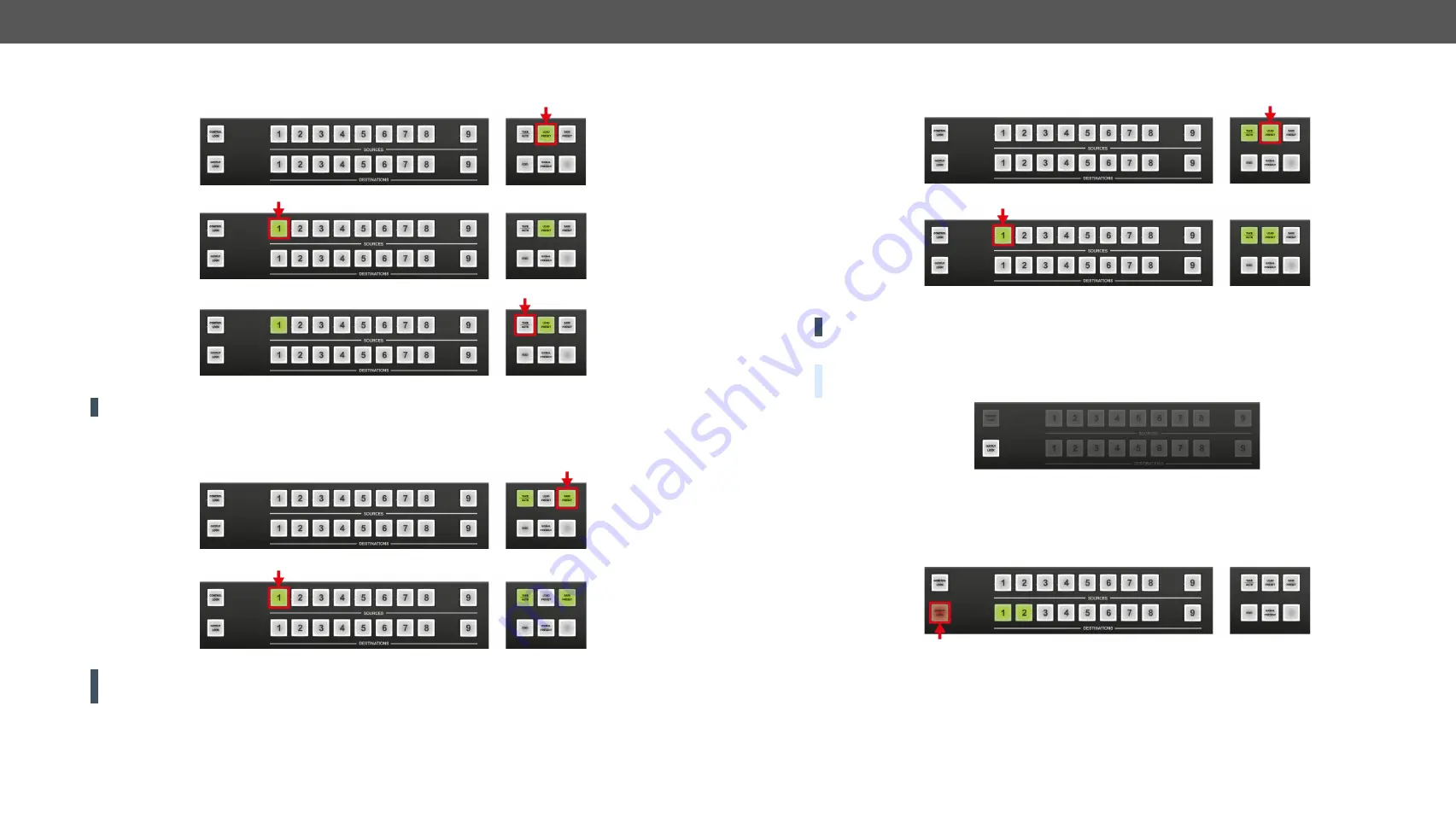
Loading a Preset in Take Mode
Step 1.
Press and release the
Load Preset
button.
Step 2.
Press and release a
source
button according to the desired memory address (source 1 to 32).
Step 3.
Press and release the
Take
button.
Now the selected preset is loaded.
ATTENTION!
Loading a preset modifies all output states that are not currently locked.
Saving a Preset in Autotake Mode
Step 1.
Create the desired connections that need to be saved.
Step 2.
Press and release the
Save Preset
button.
Step 3.
Press and release a
source
button according to the desired memory address (source 1 to 32).
Now the current configuration is stored in the selected memory.
ATTENTION!
Preset save action always stores the current configuration for all outputs including mute
state, but lock state is ignored.
Loading a Preset in Autotake Mode
Step 1.
Press and release the
Load Preset
button.
Step 2.
Press and release a
source
button according to the desired memory address (source 1 to 32).
Now the selected preset is loaded.
ATTENTION!
Loading a preset modifies all output states that are not currently locked.
4.4.8.
Output Lock
DEFINITION:
The
Output lock
means that an input port is locked to an output port and no input change or
muting can be executed on that particular output port.
Using Lightware routers it is possible to lock a destination’s state. This feature prevents an accidental
switching to the locked destination in the case of an important signal. Destinations can be independently
locked or unlocked. Locking a destination does not affect other destinations.
#lock #outputlock
View Locked Outputs in Take Mode
Step 1.
Press and release the
Output Lock
button.
Step 2.
The
Output Lock
button starts to blink and all the buttons of any locked destinations light up and
remain illuminated for three seconds.


