background image


5. Software Control – Lightware Device Controller 

DVIDL-OPT series – User's Manual 

19

5.6. 

Editing an EDID

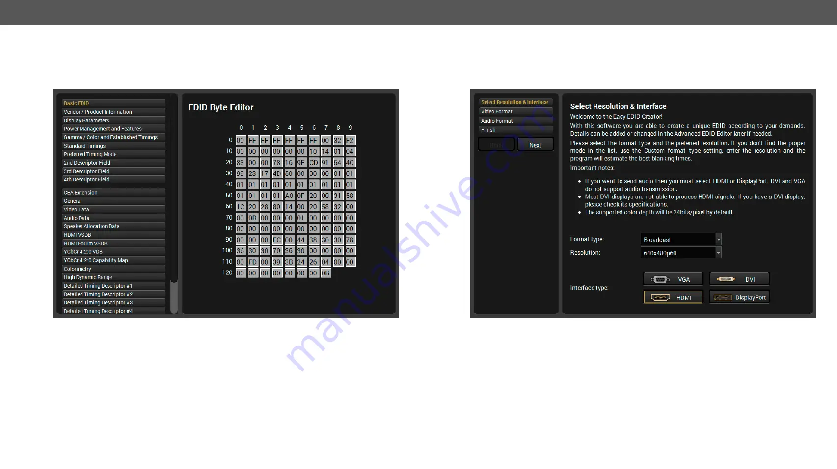
Select an EDID from Source panel and press Edit button to display Advanced EDID Editor window. The editor 

can read and write all descriptors, which are defined in the standards, including the additional CEA extension. 

Any EDID from the device’s memory or a saved EDID file can be loaded into the editor.

The EDID Editor Window

The software resolves the raw EDID and displays it as readable information to the user. All descriptors can 

be edited, and saved in an EDID file, or uploaded to the User memory. For more details about EDID Editor 

please download the 

EDID Editor Application Notes 

document.

5.6.1. 

Creating an EDID

Since above mentioned Advanced EDID Editor needs more complex knowledge about EDID, Lightware 

introduced a wizard-like interface for fast and easy EDID creation. With Easy EDID Creator it is possible to 

create custom EDIDs in four simple steps.

The Easy EDID Creator Window

By clicking on the 

Create

 button below Source panel, Easy EDID Creator is opened in a new window. For more 

details about EDID Editor please download the 

EDID Editor Application Notes 

document.

Содержание DVIDL-OPT-RX100

Страница 1: ...DVIDL OPT TX200 DVIDL OPT RX100 User s Manual Fiber Optical Multimedia Extender ...

Страница 2: ... and that no objects filled with liquids such as vases shall be placed on the apparatus No naked flame sources such as lighted candles should be placed on the apparatus Waste Electrical Electronic Equipment WEEE This marking shown on the product or its literature indicates that it should not be disposed with other household wastes at the end of its working life To prevent possible harm to the envi...

Страница 3: ...roducts Thedescriptions have been made during testing these functions in accordance with the indicated Hardware Firmware Software environment Item Version Lightware Device Controller LDC software 1 24 0 Lightware Bootloader software 3 3 3 Controller firmware DVIDL OPT TX200 1 2 3 Controller firmware DVIDL OPT RX100 1 2 2 Hardware DVIDL OPT TX200 1 1 Hardware DVIDL OPT RX100 1 0 Document revision 3...

Страница 4: ...18 5 6 Editing an EDID 19 5 6 1 Creating an EDID 19 5 7 Settings Menu 20 5 7 1 Device Information Tab 20 5 7 2 Log Tab 20 5 8 Terminal Window 21 6 PROGRAMMER S REFERENCE 22 6 1 Protocol Description 22 6 2 Status Commands 22 6 2 1 View Product Type 22 6 2 2 View Serial Number 22 6 2 3 View Firmware Version 23 6 2 4 Compile Time 23 6 2 5 View Installed Board 23 6 2 6 View Board Information 23 6 2 7 ...

Страница 5: ...I optical transmitter and DVIDL OPT RX100 is a Dual Link DVI optical receiver The appliances are suitable to extend single or dual link video signals through a single multimode fiber optical cable The appliances are assembled with Durable Neutrik opticalCON fiber connector which also accepts cables with LC connectors Front panel shows immediate feedback about the status of connected source signals...

Страница 6: ...k 1 on ly Fo r du al lin k D VI ex te ns io n us e bo th Li nk 1 an d Li nk 2 Li nk 1 Fi be r ou tp ut A Fi be r In pu t B Li nk 2 Fi be r ou tp ut B Fi be r in pu t A D V ID L O P T R X 10 0 Neutrik OpticalCON Duo hybrid up to 2500m DVIDL OPT TX200 DVIDL OPT RX100 Dual Link PC Local Monitor Dual Link Projector Dual Link DVI Dual Link DVI Dual Link DVI Standalone Application Diagram Supports 4K Re...

Страница 7: ...R ACTIVE EDID STATUS LEARN PRESS DUAL LINK DVI MULTIMODE FIBER TRANSMITTER USB CONTROL SIGNAL PRESENT SOURCE 5V 00 LOCAL MONITOR 0 0 1 1 2 2 3 3 4 4 5 5 6 6 7 7 8 8 9 9 0 0 1 1 2 2 3 3 4 4 5 5 6 6 7 7 8 8 9 9 D DV VI ID DL L O OP PT T T TX X2 20 00 0 POWER MONITOR HOTPLUG LASER ACTIVE EDID STATUS LEARN PRESS DUAL LINK DVI MULTIMODE FIBER TRANSMITTER USB CONTROL SIGNAL PRESENT SOURCE 5V 00 LOCAL MO...

Страница 8: ...ive LED Indicates when the laser driver is enabled to help avoid accidentally looking into the laser beam 5 EDID Status LED Shows the status of the selected EDID and gives feedback about EDID learning See more information in the EDID status LED section 6 Learn button Stores the EDID of the display device attached to the OUTPUT See more information in the Learning EDID section 7 Power LED Power LED...

Страница 9: ...tes if a display device or repeater etc is connected to the corresponding DVI output and it sends a valid Hot Plug Signal on Pin 16 through the DVI cable 2 Laser LEDs The LEDs indicate if a laser beam is detected on fiber connector channel A and channel B 3 Signal LED Indicates if a valid DVI clock signal can be recovered from the fiber optical signal 4 Bootload button The receiver can be switched...

Страница 10: ... high quality DVI cable for connecting sources and displays Pay attention to the DVI cable if dual link signal is to be sent use only dual link DVI cables Fiber Cable Powering As a special feature the device is able to supply 500 mA current on DDC 5V output pin 14 on the output connectors to power fiber optical DVI transmitters Standard DVI outputs or VGA cards supply only 55 mA current on 5V outp...

Страница 11: ...ns The use of universal EDID is recommended for fast and easy system setup You can find the whole list in the Factory EDID List section INFO Factory EDIDs do not include HDMI support If you need audio you can create an EDID with HDMI support with the Easy EDID Creator and upload it to user EDID memory See the Creating an EDID section for more information 4 3 Front Panel Operation Transmitter 4 3 1...

Страница 12: ...t INFO If DVIDL OPT TX200 is unable to read the monitor s EDID or there is no currently attached monitor the last attached monitor s valid EDID will be stored in the user memory INFO If the selected user memory is not empty the new EDID will overwrite the previously stored EDID 4 3 3 Deleting EDID EDID cannot be deleted by the controls on the front panel only by Lightware Device Controller softwar...

Страница 13: ... OS Available for Windows The installer can update only this instance Cannot be updated Only one updateable instance can exist for all users Different versions can be installed for all users Comparison of installation types ATTENTION Using the Normal install as the default value is highly recommended Installation for Mac OS Mount the DMG file with double clicking on it and drag the LDC icon over t...

Страница 14: ...options Log viewer The tool can be used for reviewing previously saved log files Create EDID This tool opens the Easy EDID Creator wizard which can be used for creating unique EDIDs in a few simple steps Functionality is the same as the Easy EDID Creator for the detailed information see the Creating an EDID section Demo mode This is a virtual MX FR17 matrix router with full functionality built int...

Страница 15: ...e input port of the device is on the right top the output ports are on the right bottom side The properties of input port is displayed as default Output Ports Optical and Local DVI The Output 1 is the optical module the Output 2 is the local DVI output port The laser can be enabled or disabled in the Output 1 menu DVI Input Port Window TX Optical Output Port Window TX ...

Страница 16: ...ut ports are on the right bottom side The properties of input port is displayed as default DVI Output Port If the received signal is dual link DVI the Dual link mode settings is recommended to set to Enabled for the proper operation ATTENTION Changing of Transmit current Pre emphasis Equalizer gain and PLL bandwidth settings is recommended for experienced users only Optical Input Port Window RX DV...

Страница 17: ...rce reads the EDID from the Emulated EDID memory on the INPUT port Any EDID from any of the User Factory Dynamic EDID lists can be copied to the user memory EDID Emulation Types Static EDID emulation an EDID from the Factory or User EDID list is selected Thus the Emulated EDID remains the same until the user em0ulates another EDID Dynamic EDID emulation it can be enabled by selecting a slot from t...

Страница 18: ...o the computer Step 1 Select the desired EDID from the Source panel the line will be highlighted with yellow Step 2 Press the Save button to open the dialog box and save the file to the computer Importing an EDID Previously saved EDID bin dat or edid file can be uploaded to the user memory Step 1 Press the User button on the top of the Source panel and select a memory slot Step 2 Press the Upload ...

Страница 19: ...information to the user All descriptors can be edited and saved in an EDID file or uploaded to the User memory For more details about EDID Editor please download the EDID Editor Application Notes document 5 6 1 Creating an EDID Since above mentioned Advanced EDID Editor needs more complex knowledge about EDID Lightware introduced a wizard like interface for fast and easy EDID creation With Easy ED...

Страница 20: ...heir status Step 1 Press the Download report button on the Log tab in the Settings menu Step 2 The Save as dialog box appears Select the place where you want to save the report file The default file name can be changed Step 3 LDC collects the needed information When the process is finished the folder is opened where the file was saved The report contains the following information Device type and s...

Страница 21: ...and and every received response gets an arrow or prefix and has different font colors in order to help to distinguish The timecode in every row shows the exact time when the command was sent or the response received If the Command framing checkbox is unchecked you can send multiple commands together however in this case you have to type in the framing brackets manually The terminal can be also ope...

Страница 22: ... command was successfully executed All input commands are converted to uppercase but respond commands can contain upper and lower case letters as well Legend for control commands Format Explanation loc Location number in 1 2 or 3 digit ASCII format id id number in 1 or 2 digit ASCII format id id number in 2 digit ASCII format CrLf Carriage return Line feed 0x0D 0x0A Space character 0x20 Each comma...

Страница 23: ...TE Month day and year TIME Hours minutes and seconds Format Example Command IS is Response SL 0 MB_DESC CrLf SL END CrLf SL SL 0 DVIDL OPT TX200 SCH_1 0 PCB_1 0 SL END Format Example Command FC fc Response CF DESC CrLf CF END CrLf CF DVIDL OPT TX200 FW 1 2 3 CF END 6 2 7 View All Port Status Description Shows the actual status of all input and output ports Explanation Video signal is present on th...

Страница 24: ...s 2 E Emulated EDIDs 1 Each number represents the EDID validity state for the corresponding memory location INFO If a changed EDID is queried by the WH command see the next section its value returns to 1 The status of a deleted EDID returns to 0 after query 6 3 4 View EDID Header Description Shows basic information about EDIDs in the memory Explanation Shows the EDID from memory location U14 saved...

Страница 25: ...nse EB loc B1 B2 B256 CrLf EB F1 00 FF FF FF FF FF FF 00 32 F2 00 00 00 00 00 6 3 7 Upload EDID Content to the Router Description EDID hex bytes can be written directly to the user programmable memory locations The sequence is the following Step 1 Prepare the router to accept EDID bytes to the specified location loc with command WL loc Step 2 Router responds that it is ready to accept EDID bytes w...

Страница 26: ...mpile Time 6 2 4 CT View Installed Board 6 2 5 IS View Board Information 6 2 6 FC View All Port Status 6 2 7 PS Restart the Device 6 2 8 RST Operation See in section Command Save EDID to User Memory 6 3 1 loc1 loc2 View Emulated EDID on Input 6 3 2 VEDID Watch EDID Validity Table 6 3 3 WV type View EDID Header 6 3 4 WH loc Delete EDID from Memory 6 3 5 DE loc Download EDID Content 6 3 6 WE loc Upl...

Страница 27: ... ç ç Detailed Instructions WARNING All EDIDs in the User Memory will be lost after the firmware upgrade Save the user EDIDs before processing the upgrade 7 1 Upgrading Steps in a Nutshell Step 1 Installing the Lightware Bootloader Software Step 2 Downloading and saving all the firmware files that you want to upgrade Step 3 Connecting the Lightware device and the computer via USB port and launch th...

Страница 28: ...nformation from the device If the connection is established the device is switched to bootload mode Front LEDs will show the bootload mode DVIDL OPT TX200 The EDID status LED is blinking red and green alternately DVIDL OPT RX100 The MONITOR HOTPLUG and LASER DETECT Link 1 LEDs are blinking alternately ATTENTION The bootloader application will restart the device when it establishes the connection A...

Страница 29: ...u had not selected a file for it then you will also get an information message about which file is missing Quick Bootload mode can be switched on or off any time It makes the bootloader software faster by only checking the checksum of the controller No data verification is done after writing if the checksum was correct A progress bar will show the current state of the reprogramming With some contr...

Страница 30: ...ust fit very well check all the connectors 3 5 Optical cable is plugged into incorrect connector in case of single link signal Check channel A and channel B optical connections 3 5 3 Wrong type of optical cable is used Using of Neutrik OpticalCON Duo multimode fiber cable is recommended The surface of the fiber optical cable connector became contaminated Use special fiber optical cable cleaning eq...

Страница 31: ...t EDID on an input port of the Lightware device to have a different resolution but nothing happens Solution Some graphics cards and video sources read out the EDID only after power up and later they do not sense that EDID has been changed You need to restart your source to make it read out the EDID again 9 1 2 Advanced EDID Management Each DVI sink e g monitors projectors plasma displays etc must ...

Страница 32: ...ed onto the signal Too much noise results in increased jitter Noise 9 3 Dual Link DVI signal The Dual Link DVI interface can operate in either Single Link or Dual Link mode The chosen mode depends on the pixel clock frequency of the signal and it is selected by the hardware automatically For pixel clock frequencies lower than 165 MHz Single Link mode is selected For higher pixel clock frequencies ...

Страница 33: ...wo wire pairs where one wire pair carries the odd pixels and the other wire pair carries the even pixels Video lines of the Dual Link interface INFO The colors of the wire pairs in the picture represent the color information they carry and not the color of the actual wires inside the cable TMDS clock Red even Green even Blue even Red odd Green odd PC or Mac Display Blue odd ...

Страница 34: ... format RGB Colorspace conversion No Maximum data rates 9 9 Gbps 1 65 Gbps TMDS channel Video delay 0 frame Resolution up to 4096x2400 Reclocking RX TMDS Reclocking EDID emulation TX yes Advanced EDID Management EDID memory TX yes 60 factory preset 39 user programmable EDID support TX 256 byte extended EDID v1 3 HDCP compliant No Optical Ports Connector type Neutrik NO2 4FDW type LC duplex Fiber t...

Страница 35: ...Hz D F9 1280 x 1024p 50 0 Hz D F10 1280 x 1024p 60 1 Hz D F11 1280 x 1024p 75 1 Hz D F12 1400 x 1050p 49 99 Hz D F13 1400 x 1050p 59 99 Hz D F14 1400 x 1050p 75 0 Hz D F15 1680 x 1050p 59 99 Hz D F16 1920 x 1080p 50 0 Hz D F17 1920 x 1080p 60 0 Hz D F18 2048 x 1080p 50 0 Hz D F19 2048 x 1080p 59 99 Hz D F20 1600 x 1200p 50 0 Hz D F21 1600 x 1200p 60 0 Hz D F22 1920 x 1200p 50 0 Hz D F23 1920 x 120...

Страница 36: ...tated warranty and procedures will not apply to any product that has been 2 1 Modified repaired or altered by anyone other than a certified Lightware engineer unless expressly agreed beforehand 2 2 Used in any application other than that for which it was intended 2 3 Subjected to any mechanical or electrical abuse or accidental damage 2 4 Any costs incurred for repair replacement of goods that fal...

Отзывы: