1
B
ECOMING FAMILIAR WITH THE
T
IME
C
LOCK
Front-panel push buttons permit selection of the following functions:
PROGRAM 1
Allows you to recall a series of scene changes that you have
programmed during “Set Room Change” on the clock menu. All
scene changes with Prg. 1 will be performed.
SUSPEND
When illuminated, the Time Clock will not send out any scene change
commands.
IGNORE
When illuminated, the Time Clock will not execute (skips over) the
next
scheduled command. When the command has been skipped,
this function will turn off automatically.
HOLIDAY
When illuminated, the Time Clock will, at midnight (12:00 AM), begin
executing the Holiday schedule of the current schedule- Program 1 or
Program 2. This function will turn off at this time also. (Note: This
button does not need to be pressed if tomorrow is programmed as a
holiday. Programmed holidays are handled automatically. The
purpose of this button is to instruct the Time Clock to execute the
holiday schedule for a day that is not currently programmed to be
a holiday.)
DISPLAY
When pressed, illuminated LCD window indicates time of day and date.
PROGRAM 2
Allows you to recall a series of scene changes that you have
programmed during “Set Room Change” on the clock menu. All
scene changes with Prg. 2 will be performed.
PROGRAM 1
PROGRAM 2
Susp.
Ignr.
Hol.
Disp.
5
Included with these instructions are flow charts to help guide you through step-by-step programming of the clock.
Please refer to these charts as you progress through the following instructions.
In normal operations, the Time Clock will show a standard
display reading which consists of the time, date and day
of the week.
Basic Operation
3.
To shift to the Time Clock’s main menu, press either the LEFT or RIGHT arrow button. (NOTE: You may
have to enter a password if the password feature has been enabled. See Programming, section 5.6 on page
10.) Five different functions can be accessed from the main menu:
Set room change
Review room change
Delete room change
Configure clock
Display clock
Press the LEFT or RIGHT button until the function you want is listed on the display. Then, press ENTER.
EXAMPLE: If you want to create a new room change command, press the LEFT or RIGHT button until “SET
SCENE CHANGE” appears on the display. Follow by pressing ENTER.
2
F
RONT PANEL PUSH BUTTONS
3
T
IME CLOCK MAIN MENU
Installation and
Operation
12:45 PM
7/7/99 WED
Hold
Skip
PROGRAM 1
PROGRAM 2
Hldy
Daylt
1
2
3
4
5
1
2
3
4
5
1
2
3
4
5
Signal
Net #1
Shield
Net #2
Volts DC
Ground
Scenist
1
2
3
Lytemode
1
2
3
5
4
Remote
1
2
3
5
4
CL-TCCO
1
2
3
5
4
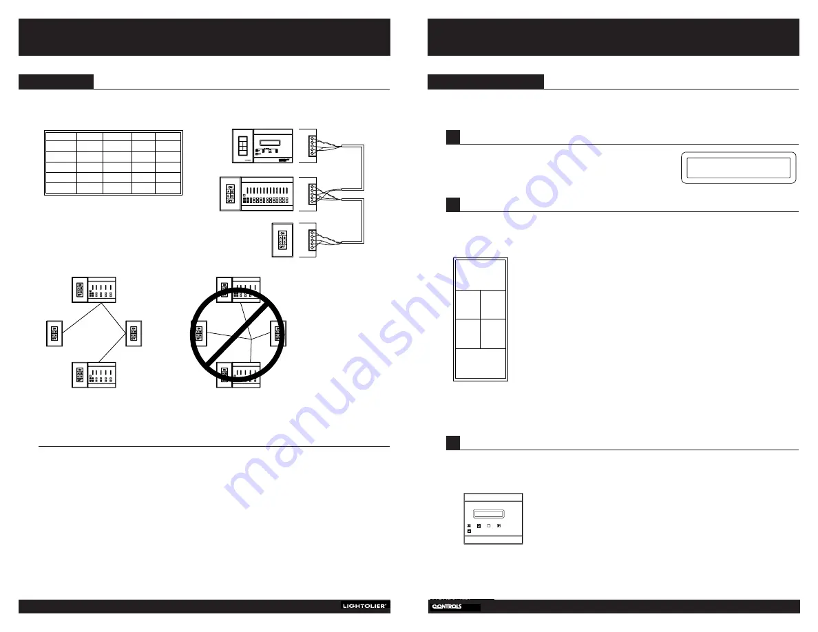
Wiring Notes:
All systems require appropriate feeds and load wiring in accordance with NEC and local electrical
code requirements.
•
Every network device should be corrected to LAN as illustrated using Belden #8777 cable.
Compli Lytemode and Network remotes are connected with four wires and the shield as shown.
•
Compli Scenists are connected with only two wires and the shield. Compli Scenists do not have connector
4 or 5. An additional pair of conductors is provided with this cable as a spare.
•
Consult your installation “Instruction Booklet” for point to point interconnection wiring diagram.
•
In Network installations that have only Compli Scenists and Network Remotes, a CL-AVPS is required to
power the Network Remotes.
•
All cable should be run in a “daisy-chain” style, from one unit to the next and to the next. Cables should
not be run “home-run” style. (See diagram)
•
BCC II wires to Time Clock via Cat 5 wire. See separate page included for the BRTLCK (P/N 85-1055).
Wiring
4
C
OMPLI
/B
RILLIANCE
II T
IME
C
LOCK
Compli
Diagram 1
Diagram 2
Does not apply to Brilliance II Time Clock.
YES NO


