background image

- 3 -

SAFETY PRECAUTIONS

Many electrical and mechanical parts in this chassis have special safety-related characteristics. These parts are identified by      in the
Schematic Diagram and Replacement Parts List. 
It is essential that these special safety parts should be replaced with the same components as recommended in this manual to prevent
Shock, Fire, or other Hazards. 
Do not modify the original design without permission of manufacturer.

General Guidance

An  isolation Transformer should always be used during the
servicing of a receiver whose chassis is not isolated from the AC
power line. Use a transformer of adequate power rating as this
protects the technician from accidents resulting in personal injury
from electrical shocks.

It will also protect the receiver and it's components from being
damaged by accidental shorts of the circuitry that may be
inadvertently introduced during the service operation.

If any fuse (or Fusible Resistor) in this TV receiver is blown,
replace it with the specified.

When replacing a high wattage resistor (Oxide Metal Film Resistor,
over 1W), keep the resistor 10mm away from PCB.

Keep wires away from high voltage or high temperature parts.

Before returning the receiver to the customer,

always perform an AC leakage current check on the exposed
metallic parts of the cabinet, such as antennas, terminals, etc., to
be sure the set is safe to operate without damage of electrical
shock. 

Leakage Current Cold Check(Antenna Cold Check)

With the instrument AC plug removed from AC source, connect an
electrical jumper across the two AC plug prongs. Place the AC
switch in the on position, connect one lead of ohm-meter to the AC
plug prongs tied together and touch other ohm-meter lead in turn to
each exposed metallic parts such as antenna terminals, phone
jacks, etc. 
If the exposed metallic part has a return path to the chassis, the
measured resistance should be between 1M

and 5.2M

When the exposed metal has no return path to the chassis the
reading must be infinite.
An other abnormality exists that must be corrected before the
receiver is returned to the customer.

Leakage Current Hot Check

(See below Figure) 

Plug the AC cord directly into the AC outlet.

Do not use a line Isolation Transformer during this check.
Connect 1.5K/10watt resistor in parallel with a 0.15uF capacitor
between a known good earth ground (Water Pipe, Conduit, etc.)
and the exposed metallic parts.
Measure the AC voltage across the resistor using AC voltmeter
with 1000 ohms/volt or more sensitivity.
Reverse plug the AC cord into the AC outlet and repeat AC voltage
measurements for each exposed metallic part. Any voltage
measured must not exceed 0.75 volt RMS which is corresponds to
0.5mA.
In case any measurement is out of the limits specified, there is
possibility of shock hazard and the set must be checked and
repaired before it is returned to the customer.

Leakage Current Hot Check circuit

1.5 Kohm/10W

To Instrument's
exposed 
METALLIC PARTS

Good Earth Ground
such as WATER PIPE,
CONDUIT etc.

AC Volt-meter

IMPORTANT SAFETY NOTICE

0.15uF

Содержание RT-37LZ55

Страница 1: ...V SERVICE MANUAL CAUTION BEFORE SERVICING THE CHASSIS READ THE SAFETY PRECAUTIONS IN THIS MANUAL CHASSIS ML 051B MODEL RZ RT 37LZ55 website http biz LGservice com e mail http www LGEservice com techsup html ...

Страница 2: ... 2 CONTENTS CONTENTS 2 PRODUCT SAFETY 3 SPECIFICATION 6 ADJUSTMENT INSTRUCTION 11 TROUBLE SHOOTING 15 BLOCK DIAGRAM 18 WIRING DIAGRAM 19 EXPLODED VIEW 20 REPLACEMENT PARTS LIST 23 SVC SHEET ...

Страница 3: ...Current Cold Check Antenna Cold Check With the instrument AC plug removed from AC source connect an electrical jumper across the two AC plug prongs Place the AC switch in the on position connect one lead of ohm meter to the AC plug prongs tied together and touch other ohm meter lead in turn to each exposed metallic parts such as antenna terminals phone jacks etc If the exposed metallic part has a ...

Страница 4: ...vely obtain and wear a commercially available discharging wrist strap device which should be removed to prevent potential shock reasons prior to applying power to the unit under test 2 After removing an electrical assembly equipped with ES devices place the assembly on a conductive surface such as aluminum foil to prevent electrostatic charge buildup or exposure of the assembly 3 Use only a ground...

Страница 5: ...not shiny reheat them and if necessary apply additional solder Fuse and Conventional Resistor Removal Replacement 1 Clip each fuse or resistor lead at top of the circuit board hollow stake 2 Securely crimp the leads of replacement component around notch at stake top 3 Solder the connections CAUTION Maintain original spacing between the replaced component and adjacent components and the circuit boa...

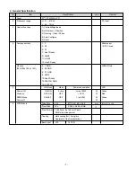
Страница 6: ...ly RZ 5 PAL N M 6 7 South America Market 6 NTSC M 7 Except South America NTSC Market RM 3 RF Input Channel VHF E2 E12 PAL UHF E21 E69 CATV S1 S20 HYPER S21 S47 L B C D FRANCE VHF 2 13 NTSC UHF 14 69 CATV 1 125 VHF Low 1 M10 JAPAN VHF High 4 S22 UHF S23 62 4 Input Voltage AC 100 240 V 50Hz 60Hz 5 Market Worldwide 6 Picture Size 940 3mm 37 02 inch 7 Tuning System FVS 100 program PAL 200 PR Option FS...

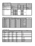
Страница 7: ...Line3 Ready D4 Jack 2 Y GND JAPAN Only 525i 525p 750p 1125i 4 Pb GND 6 Pr GND 8 LINE1 10 Line2 Ready 12 SWITCH GND 14 SWITCH 5 H V Sync Video Power consumption LED Power ON ON ON Active max 180W W Green Stand by OFF ON OFF 3 0W W Red DPMS Mode ON OFF OFF typ 30W W Green Power off W 6 LCD Module Type Size LPL 877 0 x 516 8 x 55 5 mm H x V x D Pixel Pitch LPL 0 200 x 0 600 x RGB Pixel Format 1366 ho...

Страница 8: ...0 SDTV DVD 625 Line 5 720x576 31 25 50 00 HDTV 576p 6 1280x720 45 00 60 00 HDTV 720p 7 1280x720 44 96 59 94 HDTV 720p 8 1920x1080 31 25 50 00 HDTV 1080i 50Hz AU Ver 9 1920x1080 33 75 60 00 HDTV 1080i 60Hz ATSC 10 1920x1080 33 72 59 94 HDTV 1080i 59 94Hz 5 PC INPUT Mode Table No Resolution H freq kHz V freq Hz Pixel clock MHz Proposed Analog RGB Digital RGB 1 720x400 31 468 70 8 28 321 2 640x480 31...

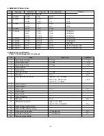
Страница 9: ...80 33 75 60 00 86 375 HDCP DVI Digital 1080i 10 1280x720 45 00 60 00 74 375 HDCP DVI Digital 720p Pin Signal Signal Level Impedance 1 Audio Output B right 0 5 Vrms 1 2 Audio Input B right 0 5 Vrms 10 3 Audio Output A left 0 5 Vrms 1 4 Ground audio 5 Ground blue 6 Audio input A left 0 5 Vrms 10 7 Blue input 0 7 V 75 8 Function Select AV control High 9 5 12V AV Mode Mid 5 8V Wide Screen 10 Low 0 2V ...

Страница 10: ... Mode Mid 5 8V Wide Screen 10 Low 0 2V TV Mode 9 Ground Green 10 Comms Data 2 11 12 Comms Data 1 13 Ground Red 14 Ground Blanking 15 Red input 16 17 Ground Video input Output 18 19 Video output Composite 1V including sync 75 20 Video input Composite 1V including sync 75 21 Common ground Shield No Item Content Remark 1 Product Dimenson Width W Length D Height H Before Packing 1061 675 269 With Stan...

Страница 11: ...0 A0 51 00 1E 30 48 88 40 35 00 BC 88 21 00 00 1C 4E 1F 00 80 51 00 1E 30 50 40 80 37 00 BC 88 21 00 00 18 00 00 00 FC 00 52 60 0A 20 20 20 00 00 00 FD 70 00 38 4B 1F 3D 09 00 0A 20 20 20 20 20 20 01 00 01 02 03 04 05 06 07 08 09 0A 0B 0C 0D 0E 0F 00 02 03 21 D1 46 85 04 02 01 03 00 23 09 07 07 23 10 09 07 07 23 09 07 07 83 01 00 00 65 03 0C 00 10 20 00 01 1D 00 80 51 D0 1C 20 40 80 35 00 BC 88 21...

Страница 12: ...ed Equipments Remote controller for adjustment MSPG 925F Pattern Generator 4 3 1 Method of Auto RGB Color Balance 1 Input the PC 1024x768 75Hz 1 2 Black White Pattern MSPG 925F model 39 pattern 18 into RGB using D sub to DVI I cable 2 Set the PSM to Standard mode in Picture menu 3 Press the ADJ key on R C for adjustment 4 Press the Vol key operate To set then it becomes automatically 5 Auto RGB OK...

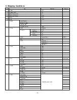
Страница 13: ...Contrast 100 Brightness 45 Colour 50 Sharpness 50 CSM Normal Cool RZ RT XD On ACM Fleshtone 1 Greentone 1 Bluetone 1 9 Sound SSM Flat SRS WOW Off AVL Off Balance 0 Treble 50 Bass 50 TV Speaker On 10 Time Clock User control Off time Off On time Off Auto sleep Off 11 Special Input TV Language English Area Management Child Lock Off Set ID 1 XD Demo To Start 12 Screen Auto config Manual config XGA Mod...

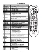
Страница 14: ...k the front AV To move channel up down or to select a function displayed on the screen To adjust the volume or accurately control a specific function To set a specific function or complete setting To move the channel down in the PIP screen To use as a red key in the teletext mode To move the channel in the PIP screen To use as a green key in the teletext mode To switch between the main and sub scr...

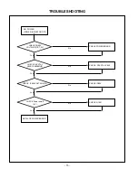
Страница 15: ...POWER INDICATOR OFF REPLACE POWER BOARD CHECK POWER BOARD CHECK CN804 VOLTAGE P ST_5V No CHECK CRYSTAL X800 CHECK CRYCTAL X800 19 6608MHZ No Yes CHECK IC806 CHECK IC806 VOLTAGE 5V No Yes CHECK Q1001 CHECK Power on off 5V No Yes Yes ...

Страница 16: ...PLACE LCD MODULE CHECK THE PERIPHERAL IC800 CHECK LVDS Output P3 PIN 21 PIN 22 No CHECK THE PERIPHERAL IC1 DOWN LOAD ISP DATA or REPLACE MAIN BOARD Check L2 12V No Yes CHECK L1022 24V CHECK R898 3 3V No Yes Yes Yes No ...

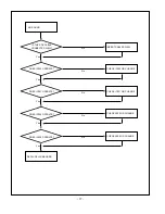
Страница 17: ...CABLES WELL IS THE SPK CABLE CONNECTED WELL No CHECK IC302 OR CHANGE DOES IC302 OPERATE No Yes CHECK IC301 OR CHANGE DOES IC301 OPERATE No Yes CHECK X300 OR CHANGE DOES IC300 OPERATE DOES IC400 OPERATE No Yes Yes Yes CHECK X400 OR CHANGE No ...

Страница 18: ...BLOCK DIAGRAM 18 ...

Страница 19: ... 19 6631T11020Z 30P 6631T20039B 15P 6631T25026C 4P 6631T20034S 4P 6631T20029S 5P 6631T25024M 3P 6631T20032G 12P WIRING DIAGRAM ...

Страница 20: ... 20 EXPLODED VIEW 010 020 101 100 060 090 060 080 070 110 120 130 140 150 050 040 030 ...

Страница 21: ...LZ55 KEY 68719ST072A PWB PCB ASSEMBLY SUB SUB T T ML051A RZ 37LZ55 IR LOGO 6871TSTA80C PWB PCB ASSEMBLY SUB SUB T T ML051B RZ 37LZ55 SIDE 49509K0023B METAL SIDE SUPPORTER RIGHT FOR 37LZ55 C SKD 49509K0024B METAL SIDE SUPPORTER LEFT FOR 37LZ55 C SKD 4950TKA361D METAL FRAME MAIN RZ 37LZ55 C SKD 6709900002A POWER SUPPLY ASSEMBLY FREE TORNADO 37 LCD KN HE YY 33139P3004A MAIN TOTAL ASSEMBLY RZ 37LZ55 B...

Страница 22: ...8OHM 10 15W DB 110 32LG10 68719ST071A PWB PCB ASSEMBLY SUB SUB T T ML051A RZ 37LZ55 KEY 68719ST072A PWB PCB ASSEMBLY SUB SUB T T ML051A RZ 37LZ55 IR LOGO 6871TSTA80C PWB PCB ASSEMBLY SUB SUB T T ML051B RZ 37LZ55 SIDE 49509K0023A METAL SIDE SUPPORTER RIGHT FOR 37LZ55 49509K0023B METAL SIDE SUPPORTER RIGHT FOR 37LZ55 C SKD 49509K0024A METAL SIDE SUPPORTER LEFT FOR 37LZ55 49509K0024B METAL SIDE SUPPO...

Страница 23: ...S AL LOC NO PART NO DESCRIPTION SPECIFICATION C1155 0CH3104K566 0 1UF 50V 10 X7R 2012 R TP C1156 0CH3103K516 10000PF 50V 10 B Y5P 2012 C1159 0CH3103K516 10000PF 50V 10 B Y5P 2012 C116 0CH3103K516 10000PF 50V 10 B Y5P 2012 C1160 0CH3104K566 0 1UF 50V 10 X7R 2012 R TP C1162 0CH3103K516 10000PF 50V 10 B Y5P 2012 C1163 0CH3104K566 0 1UF 50V 10 X7R 2012 R TP C1165 0CH3103K516 10000PF 50V 10 B Y5P 2012 ...

Страница 24: ...CH3104K566 0 1UF 50V 10 X7R 2012 R TP C1413 0CH3103K516 10000PF 50V 10 B Y5P 2012 C1414 0CH3104K566 0 1UF 50V 10 X7R 2012 R TP DATE 2005 09 21 S AL LOC NO PART NO DESCRIPTION SPECIFICATION C204 0CH3103K516 10000PF 50V 10 B Y5P 2012 RZ 37LZ55 C205 0CH3103K516 10000PF 50V 10 B Y5P 2012 RZ 37LZ55 C247 0CH3104K566 0 1UF 50V 10 X7R 2012 R TP C248 0CH3104K566 0 1UF 50V 10 X7R 2012 R TP C256 0CH3104K566 ...

Страница 25: ...33 0CH3104K566 0 1UF 50V 10 X7R 2012 R TP C1034 0CH3103K516 10000PF 50V 10 B Y5P 2012 DATE 2005 09 21 S AL LOC NO PART NO DESCRIPTION SPECIFICATION C107 0CH3104K566 0 1UF 50V 10 X7R 2012 R TP C1102 0CH3103K516 10000PF 50V 10 B Y5P 2012 C1103 0CH3103K516 10000PF 50V 10 B Y5P 2012 C1111 0CH3104K566 0 1UF 50V 10 X7R 2012 R TP C1164 0CH3103K516 10000PF 50V 10 B Y5P 2012 C119 0CH3103K516 10000PF 50V 10...

Страница 26: ...6 0CH6102K406 1000PF 50V 5 SL 2012 R TP C617 0CH6102K406 1000PF 50V 5 SL 2012 R TP C618 0CH6102K406 1000PF 50V 5 SL 2012 R TP DATE 2005 09 21 S AL LOC NO PART NO DESCRIPTION SPECIFICATION C619 0CH6102K406 1000PF 50V 5 SL 2012 R TP C620 0CH6102K406 1000PF 50V 5 SL 2012 R TP C621 0CH6102K406 1000PF 50V 5 SL 2012 R TP C622 0CH6102K406 1000PF 50V 5 SL 2012 R TP C623 0CH6102K406 1000PF 50V 5 SL 2012 R ...

Страница 27: ... 22UF MVK 16V 20 R TP SMD C230 0CE226WF6DC 22UF MVK 16V 20 R TP SMD C233 0CE106VF6DC 10UF MV 16V 20 R TP SMD S C235 0CE107WF6DC 100UF MVK 16V 20 R TP SMD RZ 37LZ55 C236 0CE107WF6DC 100UF MVK 16V 20 R TP SMD DATE 2005 09 21 S AL LOC NO PART NO DESCRIPTION SPECIFICATION C249 0CE107WF6DC 100UF MVK 16V 20 R TP SMD C252 0CE105VK6DC 1UF MV 50V 20 R TP SMD SM RT 37LZ55 C253 0CE105VK6DC 1UF MV 50V 20 R TP...

Страница 28: ... IC604 0ISTLFA058A 74F14SCX FAIRCHILD 14P SOIC DATE 2005 09 21 S AL LOC NO PART NO DESCRIPTION SPECIFICATION L303 6140VB0022A CPS 0810 GET 22UH 21 5TURNS L304 6140VB0022A CPS 0810 GET 22UH 21 5TURNS L305 6140VB0022A CPS 0810 GET 22UH 21 5TURNS L306 6140VB0022A CPS 0810 GET 22UH 21 5TURNS L110 6210TCE001L HB 1T2012 102JT CERATECH 20 AR601 6210TCE002B HB 4M3216 121JT CERATECH 32 AR602 6210TCE002B HB...

Страница 29: ... 2SA1504S ASY BK KEC Q105 0TR387500AA CHIP 2SC3875S ALY BK KEC Q107 0TR387500AA CHIP 2SC3875S ALY BK KEC Q108 0TR150400BA CHIP 2SA1504S ASY BK KEC DATE 2005 09 21 S AL LOC NO PART NO DESCRIPTION SPECIFICATION Q109 0TR150400BA CHIP 2SA1504S ASY BK KEC Q113 0TR387500AA CHIP 2SC3875S ALY BK KEC Q210 0TR387500AA CHIP 2SC3875S ALY BK KEC RT 37LZ55 Q211 0TR387500AA CHIP 2SC3875S ALY BK KEC RT 37LZ55 Q21...

Страница 30: ...1 10 W 2012 5 00 RZ 37LZ55 R241 0RH0752D622 75 OHM 1 10 W 2012 5 00 RZ 37LZ55 R243 0RH0000D622 0 OHM 1 10 W 2012 5 00 D RZ 37LZ55 R243 0RH0752D622 75 OHM 1 10 W 2012 5 00 RT 37LZ55 R244 0RH0000D622 0 OHM 1 10 W 2012 5 00 D RZ 37LZ55 DATE 2005 09 21 S AL LOC NO PART NO DESCRIPTION SPECIFICATION R245 0RH0752D622 75 OHM 1 10 W 2012 5 00 RZ 37LZ55 R246 0RH0000D622 0 OHM 1 10 W 2012 5 00 D RZ 37LZ55 R2...

Страница 31: ...10 W 2012 5 00 D DATE 2005 09 21 S AL LOC NO PART NO DESCRIPTION SPECIFICATION R913 0RH1001D622 1K OHM 1 10 W 2012 5 00 R920 0RH1002D622 10K OHM 1 10 W 2012 5 00 R921 0RH1002D622 10K OHM 1 10 W 2012 5 00 R931 0RH1002D622 10K OHM 1 10 W 2012 5 00 R936 0RH1001D622 1K OHM 1 10 W 2012 5 00 R937 0RH1001D622 1K OHM 1 10 W 2012 5 00 R941 0RH1002D622 10K OHM 1 10 W 2012 5 00 R942 0RH1002D622 10K OHM 1 10 ...

Страница 32: ...H1000D622 100 OHM 1 10 W 2012 5 00 R451 0RH1000D622 100 OHM 1 10 W 2012 5 00 R456 0RH1000D622 100 OHM 1 10 W 2012 5 00 DATE 2005 09 21 S AL LOC NO PART NO DESCRIPTION SPECIFICATION R457 0RH2200D622 220 OHM 1 10 W 2012 5 00 R458 0RH0000D622 0 OHM 1 10 W 2012 5 00 D R460 0RH5600D622 560 OHM 1 10 W 2012 5 00 R461 0RH0472D622 47 OHM 1 10 W 2012 5 00 R463 0RH3901D622 3 9K OHM 1 10 W 2012 5 00 R464 0RH0...

Страница 33: ...ANG 19 6608MHZ TU100 6700MF0012C TAFM W103P LGIT MULTI FS PH SW1201 140 313B TACT 2LEAD 160G TA LG C D DATE 2005 09 21 S AL LOC NO PART NO DESCRIPTION SPECIFICATION SW1202 140 313B TACT 2LEAD 160G TA LG C D SW1203 140 313B TACT 2LEAD 160G TA LG C D SW1204 140 313B TACT 2LEAD 160G TA LG C D SW1205 140 313B TACT 2LEAD 160G TA LG C D SW1206 140 313B TACT 2LEAD 160G TA LG C D SW1207 140 313B TACT 2LEA...

Страница 34: ......

Страница 35: ...Sep 2005 Printed in Korea P NO 38289S0022F ...

Отзывы: