background image

IC Remove/Replacement
Some chassis circuit boards have slotted holes (oblong) through
which the IC leads are inserted and then bent flat against the
circuit foil. When holes are the slotted type, the following technique
should be used to remove and replace the IC. When working with
boards using the familiar round hole, use the standard technique
as outlined in paragraphs 5 and 6 above.

Removal
1.  Desolder and straighten each IC lead in one operation by gently

prying up on the lead with the soldering iron tip as the solder
melts.

2.  Draw away the melted solder with an anti-static suction-type

solder removal device (or with solder braid) before removing the
IC.

Replacement
1.  Carefully insert the replacement IC in the circuit board.
2.  Carefully bend each IC lead against the circuit foil pad and

solder it.

3.  Clean the soldered areas with a small wire-bristle brush.

(It is not necessary to reapply acrylic coating to the areas).

"Small-Signal" Discrete Transistor
Removal/Replacement
1.  Remove the defective transistor by clipping its leads as close as

possible to the component body.

2.  Bend into a "U" shape the end of each of three leads remaining

on the circuit board.

3.  Bend into a "U" shape the replacement transistor leads.
4.  Connect the replacement transistor leads to the corresponding

leads extending from the circuit board and crimp the "U" with
long nose pliers to insure metal to metal contact then solder
each connection.

Power Output, Transistor Device
Removal/Replacement
1.  Heat and remove all solder from around the transistor leads.
2. Remove the heat sink mounting screw (if so equipped).
3.  Carefully remove the transistor from the heat sink of the circuit

board.

4.  Insert new transistor in the circuit board.
5. Solder each transistor lead, and clip off excess lead.
6.  Replace heat sink.

Diode Removal/Replacement
1.  Remove defective diode by clipping its leads as close as

possible to diode body.

2.  Bend the two remaining leads perpendicular y to the circuit

board.

3.  Observing diode polarity, wrap each lead of the new diode

around the corresponding lead on the circuit board.

4.  Securely crimp each connection and solder it.
5.

Inspect (on the circuit board copper side) the solder joints of

the two "original" leads. If they are not shiny, reheat them and if
necessary, apply additional solder.

Fuse and Conventional Resistor
Removal/Replacement
1.  Clip each fuse or resistor lead at top of the circuit board hollow

stake.

2.  Securely crimp the leads of replacement component around

notch at stake top.

3.  Solder the connections.

CAUTION: Maintain original spacing between the replaced
component and adjacent components and the circuit board to
prevent excessive component temperatures.

Circuit Board Foil Repair
Excessive heat applied to the copper foil of any printed circuit
board will weaken the adhesive that bonds the foil to the circuit
board causing the foil to separate from or "lift-off" the board. The
following guidelines and procedures should be followed whenever
this condition is encountered.

At IC Connections
To repair a defective copper pattern at IC connections use the
following procedure to install a jumper wire on the copper pattern
side of the circuit board. (Use this technique only on IC
connections).

1.  Carefully remove the damaged copper pattern with a sharp

knife. (Remove only as much copper as absolutely necessary).

2.  carefully scratch away the solder resist and acrylic coating (if

used) from the end of the remaining copper pattern.

3.  Bend a small "U" in one end of a small gauge jumper wire and

carefully crimp it around the IC pin. Solder the IC connection.

4.  Route the jumper wire along the path of the out-away copper

pattern and let it overlap the previously scraped end of the good
copper pattern. Solder the overlapped area and clip off any
excess jumper wire.

At Other Connections
Use the following technique to repair the defective copper pattern
at connections other than IC Pins. This technique involves the
installation of a jumper wire on the component side of the circuit
board.

1.  Remove the defective copper pattern with a sharp knife.

Remove at least 1/4 inch of copper, to ensure that a hazardous
condition will not exist if the jumper wire opens.

2.  Trace along the copper pattern from both sides of the pattern

break and locate the nearest component that is directly
connected to the affected copper pattern.

3.  Connect insulated 20-gauge jumper wire from the lead of the

nearest component on one side of the pattern break to the lead
of the nearest component on the other side.
Carefully crimp and solder the connections.
CAUTION: Be sure the insulated jumper wire is dressed so the
it does not touch components or sharp edges.

Содержание RM-20LA70

Страница 1: ...G THE CHASSIS READ THE SAFETY PRECAUTIONS IN THIS MANUAL CHASSIS ML 041B MODEL RM 20LA70 RM 20LA70 Rev A website http biz LGservice com e mail http www LGEservice com techsup html ID LABEL Model No Same looking with new chassis Issue Date 2004 06 ...

Страница 2: ...TS CONTENTS 2 PRODUCT SAFETY 3 SPECIFICATION 6 ADJUSTMENT INSTRUCTION 10 TROUBLE SHOOTING 12 BLOCK DIAGRAM 17 WIRING DIAGRAM 19 EXPLODED VIEW 20 EXPLODED VIEW PARTS LIST 21 REPLACEMENT PARTS LIST 22 SVC SHEET ...

Страница 3: ...t such as antennas terminals etc to be sure the set is safe to operate without damage of electrical shock Leakage Current Cold Check Antenna Cold Check With the instrument AC plug removed from AC source connect an electrical jumper across the two AC plug prongs Place the AC switch in the on position connect one lead of ohm meter to the AC plug prongs tied together and touch other ohm meter lead in...

Страница 4: ...ely obtain and wear a commercially available discharging wrist strap device which should be removed to prevent potential shock reasons prior to applying power to the unit under test 2 After removing an electrical assembly equipped with ES devices place the assembly on a conductive surface such as aluminum foil to prevent electrostatic charge buildup or exposure of the assembly 3 Use only a grounde...

Страница 5: ...t shiny reheat them and if necessary apply additional solder Fuse and Conventional Resistor Removal Replacement 1 Clip each fuse or resistor lead at top of the circuit board hollow stake 2 Securely crimp the leads of replacement component around notch at stake top 3 Solder the connections CAUTION Maintain original spacing between the replaced component and adjacent components and the circuit board...

Страница 6: ...ical Interface Color Depth Size mm Surface Treatment Operating Mode Back light Unit R T Typ Maker Type ActiveDisplay Area Pixel Pitch mm Electrical Interface Color Depth Size mm Surface Treatment Operating Mode Back light Unit R T Typ LPL TFT Color LCD Module 20 1 inches 380 16mm diagonal Aspect 4 3 0 6375mm H x0 6375mm V xRGB TTL 8BIT 16 777 216 colors 450 H x 348 7 V x20 D Glare Hard Coating 3H ...

Страница 7: ...1 1 NO NO BG DK BG I LL BG DK BG I LL X X O X O X X X X O O X X Item Specification Remark No Top option PAL NTSC Rear Rear Rear option NT Rear option EU Rear 5 Optical Character Item Remark Specification Viewing Angle CR 10 Luminance Contrast Ratio CIE Color Coordinates Typical MAX MIN ALL white All black R L U D Luminance cd Variation LPL 85 85 85 85 400 1 3 400 0 289 0 335 0 692 0 335 0 289 0 58...

Страница 8: ...3 H Sync 15 SCL 1 Contrast Brightness 2 H Position V Position 3 Tracking Clock Phase 4 Auto Configure RESET 1 Y 3 Pb 5 Pr 1 Y GND 2 Pb 5 Pr 7 LINE1 Ready 9 Line2 11 Line3 13 Line3 ready 2 Green 4 ID2 GND 6 RED GND 8 Blue GND 10 D GND 12 SDA 14 V Sync Shell GND 2 Y GND 4 Pb GND 6 Pr GND 8 LINE1 10 Line2 Ready 12 SWITCH GND 14 SWITCH Remark 10 Digital GND Middle east NTSC Area JAPAN Only Video Activ...

Страница 9: ...on Audio Input Dynamic Range Video Output Level Video Output Frequency Response Video Output S N Audio Output Level Audio Output Frequency Response Audio Output S N Audio Output Distortion Video Input Level R G B Video Input Level Component Y PB PR RGB Input Resolution Vertical RGB Input Resolution Horizontal RGB Input Horizontal Frequency RGB Input Frame Rate 0 85 0 4 0 1 40 2 0 85 3 8 40 0 4 0 1...

Страница 10: ...ress IN START Key twice Once the adjustment is completed press the Enter Key to save and finish the adjustment 2 2 2 Component Mode adjustment 2 2 2 1 Adjustment preparation Conduct Heat Run at the RF fog signals for more than 30 minutes Connect the Pattern Generator to the Component Jack Y Pb Pr of LCD TV 2 2 2 2 Auto Gain Offset adjustment Convert the input mode to the component input Using the ...

Страница 11: ...the front AV To move channel up down or to select a function displayed on the screen To adjust the volume or accurately control a specific function To set a specific function or complete setting To move the channel down in the PIP screen To use as a red key in the teletext mode To move the channel in the PIP screen To use as a green key in the teletext mode To switch between the main and sub scree...

Страница 12: ... short of main B D or Change Lips Change IC1107 IC1104 Change LED Assy Check 15V or 5V of Lips Check Output of IC1107 IC104 Check LED Assy Check P1100 P210 Connector Fail Fail Change Q1100 Check Output of Q1100 Fail Pass Fail Pass Pass Pass A Process ...

Страница 13: ...eck inverter Connector or inverter Check input source cable and jack Repeat A PROCESS Fail Change L900 L901 L902 L903 Fail Change IC901 Fail Change inverter connector or inverter Fail Change panel link cable or module Fail Change module Fail Check panel link Cable or module Pass Pass Pass Pass B Process ...

Страница 14: ... Check the input output of IC1 Check the input output of IC901 Check input source cable and jack Fail Re soldering or Change the defect part Check X11 Fail Re soldering or Change the defect part Check X900 Fail Pass Pass Pass Check the input output of IC800 IC851 Re soldering or Change the defect part Fail Pass ...

Страница 15: ...e input output of IC1 Check the input output of IC800 IC851 Check input source cable and jack Fail Fail Fail Fail Re soldering or Change the defect part Chek X11 Fail Re soldering or Change the defect part Check 5V 33V of TU1000 Re soldering or Change the defect part Pass Pass Pass Check the input output of IC901 Fail Re soldering or Change the defect part Check X900 Pass Pass ...

Страница 16: ... Check the input source Fail Pass Re soldering or Change the defect part Check X11 Check the input output of IC1 Fail Pass Re soldering or Change the defect part Check the input output of IC100 IC101 Fail Pass Change speaker Check the speaker Fail Pass ...

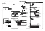
Страница 17: ...851 LA7222 IC2 TC90A65F IC500 14066 IC202 D SUB AT24C16 IC4 DIGITAL SIGNAL SOUND INPUT IF INPUT ANALOG SIGNAL SOUND OUTPUT ML 041B Block Diagram POWER IF PC SIDE_AV L R SIDE_L R PC L R L R AUDIO S A W Z1000 SCART V L R S VHS H P V SCART R G B SIDE V Y P b P r RGB OUT TTL 1 OUT TTL 2 OUT LVDS 1 O UT PC RGB COMPONENT ...

Страница 18: ...nt to the LCD module as a TTL output VCTi is the main microprocessor that handles video signal processing and sound signal processing It also manages the RF signals received from the tuner The scaler can control timing to fit into the LCD panel and can also control the size and position of the input signal 2 Power Supply Unit The power supply unit provides 15V and 5V DC power to the mainboard The ...

Страница 19: ...5MM H B 220MM 1 20P LVDS 200MM 2 41P TTL 3 50P TTL 145MM 4P_2 5MM SHIELD RECEPTERCLE GND 2PIN 4PIN 500MM 750MM 1 6 7 5 2 3 4 8 9 P904 P902 P901 WIRING DIAGRAM No Part No 1 2 3 4 5 6 7 8 Wiring Part List 6631T25019Y 6631T11017P CMO 6631T11017Q AUO 6631T11021A 6631T11012R 6631T20028G 6631T20029X 6631T25021A 6620K00007C or 6620K00007A ...

Страница 20: ...EXPLODED VIEW 1 2 3 5 5 6 8 7 4 10 9 11 13 14 12 15 16 17 18 19 20 22 21 ...

Страница 21: ...9 3313TP2019A MAIN TOTAL ASSEMBLY RM 20LA77 BRAND ML 041B 10 6871TPT280A PWB PCB ASSEMBLY POWER RM 20LA77 POWER TOTAL LIEN CHANG LIPS FOR CMO AUO 11 6871TST561A PWB PCB ASSEMBLY SUB RM 20LA70 ML 041B SUB TOTAL BRAND JACK DVD BOARD ASSY 12 4951TKK186A METAL ASSEMBLY SHIELD REAR RM 20LA77 13 4950TKK916A METAL PLATE 15 20LA70 REAR A V B T 14 4810V00925B BRACKET REAR AV RZ 15LA70 ML024E HIPS 15 5020V0...

Страница 22: ...C930 0CH3104K946 100000PF 50V Z F 2012 R TP C934 0CH3104K946 100000PF 50V Z F 2012 R TP C935 0CH3104K946 100000PF 50V Z F 2012 R TP C936 0CH3104K946 100000PF 50V Z F 2012 R TP C937 0CH3104K946 100000PF 50V Z F 2012 R TP C938 0CH3104K946 100000PF 50V Z F 2012 R TP C939 0CH3104K946 100000PF 50V Z F 2012 R TP C940 0CH3104K946 100000PF 50V Z F 2012 R TP C943 0CH3104K946 100000PF 50V Z F 2012 R TP C944...

Страница 23: ...P NP0 C47 0CC220CK41A 22PF 1608 50V 5 R TP NP0 C48 0CC220CK41A 22PF 1608 50V 5 R TP NP0 C53 0CC102CK41A 1000PF 1608 50V 5 R TP NP0 C56 0CC221CK41A 220PF 1608 50V 5 R TP NP0 DATE 2004 06 16 S AL LOC NO PART NO DESCRIPTION SPECIFICATION C57 0CC221CK41A 220PF 1608 50V 5 R TP NP0 C58 0CC221CK41A 220PF 1608 50V 5 R TP NP0 C74 0CC102CK41A 1000PF 1608 50V 5 R TP NP0 C83 0CC102CK41A 1000PF 1608 50V 5 R TP...

Страница 24: ... Q603 0TR387500AA CHIP 2SC3875S ALY BK KEC Q100 0TR387500AA CHIP 2SC3875S ALY BK KEC Q1000 0TR388109AA KTC3881 CHIP TP KEC Q101 0TR150400BA CHIP 2SA1504S ASY BK KEC Q1100 0TR387500AA CHIP 2SC3875S ALY BK KEC Q1151 0TR387500AA CHIP 2SC3875S ALY BK KEC DATE 2004 06 16 S AL LOC NO PART NO DESCRIPTION SPECIFICATION Q12 0TR150400BA CHIP 2SA1504S ASY BK KEC Q13 0TR150400BA CHIP 2SA1504S ASY BK KEC Q14 0...

Страница 25: ...77 100 OHM 1 10 W 5 1608 R TP R50 0RJ1000D677 100 OHM 1 10 W 5 1608 R TP R51 0RJ1000D677 100 OHM 1 10 W 5 1608 R TP DATE 2004 06 16 S AL LOC NO PART NO DESCRIPTION SPECIFICATION R52 0RJ1000D677 100 OHM 1 10 W 5 1608 R TP R53 0RJ1500D677 150 OHM 1 10 W 5 1608 R TP R54 0RJ1000D677 100 OHM 1 10 W 5 1608 R TP R55 0RJ1500D677 150 OHM 1 10 W 5 1608 R TP R56 0RJ1000D677 100 OHM 1 10 W 5 1608 R TP R58 0RJ...

Страница 26: ...0V J NP0 2012 R TP C1220 0CH6331K416 330PF 50V J NP0 2012 R TP C1215 0CH3103K516 10000PF 50V 10 B Y5P 2012 R C1216 0CH3103K516 10000PF 50V 10 B Y5P 2012 R L1206 6210TCE001A HB 1S2012 080JT CERATEC 2012M L1207 6210TCE001A HB 1S2012 080JT CERATEC 2012M L1208 6210TCE001A HB 1S2012 080JT CERATEC 2012M L1211 6210TCE001A HB 1S2012 080JT CERATEC 2012M L1213 6210TCE001A HB 1S2012 080JT CERATEC 2012M L1214...

Страница 27: ......

Страница 28: ......

Страница 29: ...Jun 2004 Printed in Korea P NO 3828TSL103N ...

Отзывы: