ipLDK-60 SERVICE MANUAL
DIGITAL KEY TELEPHONE SYSTEM
6
1.5 System Configuration
1.5.1 System Configuration
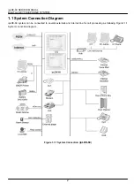
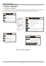
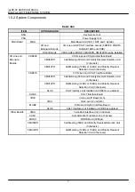
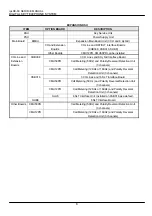
The following Figure 1.2.1 System connection diagram shows the ipLDK-60 system configuration for all kinds of board
in this system that includes the existing boards for the ipLDK-60 system and the developed new boards.
Figure 1.2.1 System Configuration
`
BKSU
: Basic Key System Unit
MBU : Main Board Unit
(3CO+1DKT+7Hybrid ports)
PSU
: Power Supply Unit (90W)
Basic KSU
VMIU
: Voice Mail Interface Unit (4 chs)
Other Option Boards
: 33 Kbps Modem (1 Port)
: 3 CO & 8 Hybrid (8DKTs & 8SLTs)
MODU
CHB308
CSB316
SLIB8
: 3 CO & 16 SLTs
: 8 SLT Port
: 50Hz/12 or 16kHz Call Metering Unit
& Polarity Reversal Detection(3 chs)
CMU50PR/
12PR
Expansion KSU
EKSU
: Expansion Key System Unit
EMBU
(3CO+8Hybrid ports)
: Expansion Main Board Unit
PSU
: Power Supply Unit (90W)
Terminals
Digital KTU
: LDP -6012D & LDP-6030D
LIP-6212D & LIP-6230D
LDP-DSS, LDP-DPB
SLTs, FAX, Modem, RS-232C, LAN
External Page & External MOH
: Auto Attendant Function Unit (4 chs)
AAFU
E1HB :
E1R2 and 8 Hybrid


