3-43
3-44
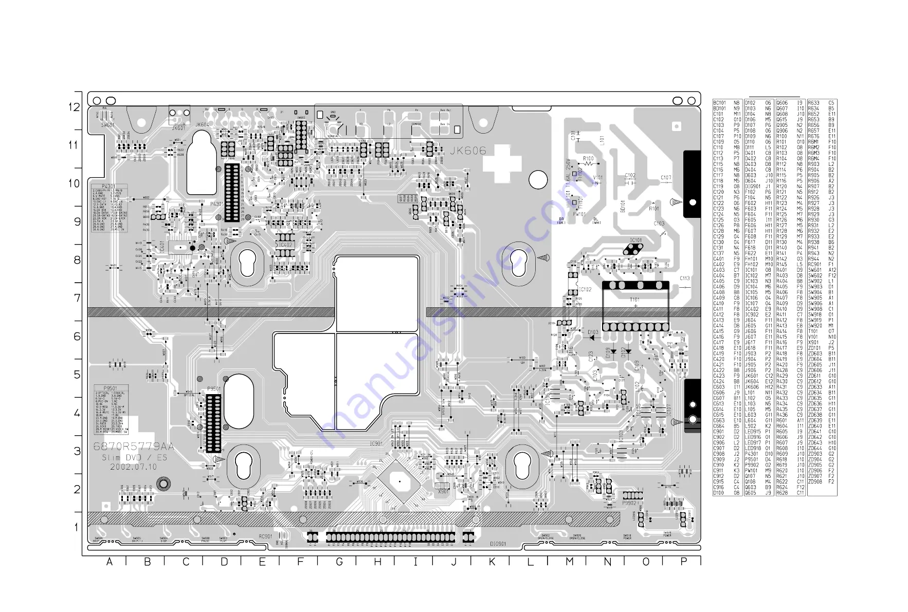
2. POWER, A/V, FRONT P.C.BOARD
LOCATION GUIDE
Страница 1: ...3 43 3 44 2 POWER A V FRONT P C BOARD LOCATION GUIDE ...
Страница 2: ...PRINTED CIRCUIT DIAGRAMS 1 MAIN P C BOARD LOCATION GUIDE TOP SIDE BOTTOM SIDE 3 41 3 42 ...
Страница 3: ...AYS WHEN THE HIGH VOLTAGE IS AT THE FACTORY SPECIFIED LEVEL THE PROPER VALUE IS GIVEN IN THE APPLICABLE SCHEMATIC OPERA TION AT HIGHER VOLTAGES MAY CAUSE A FAILURE OF THE PIC TURE TUBE OR HIGH VOLTAGE SUPPLY AND UNDER CERTAIN CIR CUMSTANCES MAY PRODUCE RADIATION IN EXCESS OF DESIR ABLE LEVELS 2 ONLY FACTORY SPECIFIED C R T ANODE CONNECTORS MUST BE USED DEGAUSSING SHIELDS ALSO SERVE AS X RAY SHIELD...
Страница 4: ... pan els Input terminals Earphone jacks etc Electrostatically Sensitive ES Devices Some semiconductor solid state devices can be damaged easily by static electricity Such components commonly are called Electrostatically Sensitive ES Devices Examples of typical ES devices are integrated circuits and some field effect transistors and semiconductor chip components The following techniques should be u...
Страница 5: ...used to secure metal parts If they are used improperly the screw holes will be easily damaged and the parts can not be fixed A A A A A Top Case A A Tray Door Disc Tray Fig 2 3 Stopper Stopper Stopper Front Panel OPTIONAL PART CABINET DISASSEMBLY 1 Top Case 1 Release 7 screws A See Fig 2 1 2 Lift the top case with holding the back of it and remove it in the direction of the arrow Fig 2 1 Fig 2 2 Fi...
Страница 6: ... 3 Remove the Deck from Main Circuit Board 4 Remove Main Circuit Board from Interface Board 5 Remove 2 screw C 6 Remove Interface Board from the chassis CIRCUIT BOARD DISASSEMBLY Note Before removing the main circuit board be sure to shortcircuit the laserdiode output land After replacing the main circuit board open the land after inserting the flexible connector Refer to Mechanism Disassembly ...
Страница 7: ...5V_A 24VA F RECTIFIER LINE FIL TER SWITCHING TR TRANS FEED B REG 8V 8V 5 2VA F RECTIFIER FLD RECTIFIER 9V RECTIFIER 5 2V LPF LPF RECTIFIER 14V LPF 12VA AC90 240V PWR ON OFF REG 3 3V REG 3 3V 3 3V_M1 3 3V 3 3V_M DV5000 s DV6000 s 3 14 ...
Страница 8: ...k ing l o a di ng sled Spi ndle M D PICK UP MCK IC206 HDC25D811 CD DVD DSP DVD SERVO IC2A1 HD153702TF RF Signal Process or FDO TDO FMO L oad open close loading control UCOM I F DVD A B C D FE TE PI SBADD 4 DVD CD RF IC203 1M x 16bit SDRAM 16 9 ICADDR 0 8 ICDAT A 00 15 DO 0 7 AO 0 5 DVD_DATA 0 7 MON MDP SPINDLE_FG MPEG I F 2 DSP_ CS WR RD 3 8 DV5000 s DV6000 s 3 RF CD DSP DVD DSP DVD SERVO Block Di...
Страница 9: ...CK DA_DAT A0 DA_BCK DA_XCK FL FR RL RR WOOFER CENTER L R U COM I F IC452 L PF K A 5532 OP A MP IC453 L PF KA 5532 OP A MP IC454 L PF KA 5532 OP A MP IC451 PCM1603KY Aud i o DAC 5 1CH FL FR RL RR WOOFER CENTER L R A V JACK I F DAC_RST S_DATA S_CL K DAC_L1 DA_L RCK DA_DAT A 1 3 DA_BCK DA_XCK MPEG I F MPEG I F U COM I F DV5000 s DV6000 s 3 16 ...
Страница 10: ...TA SQCK SQS0 REQP SDCL K1 PSYNC DSP_ INT SENSE DSP_ CS AD 04 21 RF MOTOR I F MI RR L DON SCL K S DAT A EE_CS F_IN 32 MD 00 31 MCL K2 CKE MA 00 10 MA 12 13 CS0 RAS CAS WE DQM 0 3 SPINDLE_FG ALE AD 04 19 16 L ADD 04 19 16 LA 0 3 4 AD 00 15 16 AUDIO I F DA_DAT A 0 3 DA_BCK DA_LRCK DA_XCK 4 DAC_L0 DAC_L1 DAC_RST A V JACK I F C R B CVBS G R Y B G CVBS V_MUTE 16 9 ZISENB RD PWED IC301 DV5000 s DV6000 s ...
Страница 11: ...connected at this time MICON recoguizes the connection and prepares the compo sition of external voice and internal melody 3 The week signal of the microphone is converted to the digital signal after voice output that has passed through PREAMP BA3308 and AMP KIA4558 passes through CS5331 that is Audio ADC Analog to Digital convertor 4 This digital signal enters NS that is MPEG IC and is added to t...
Страница 12: ...IS CIRCUIT DIAGRAM MAY OCCASIONALLY DIF FER FROM THE ACTUAL CIRCUIT USED THIS WAY IMPLEMENTATION OF THE LATEST SAFETY AND PERFORMANCE IMPROVEMENT CHANGES INTO THE SET IS NOT DELAYED UNTIL THE NEW SERVICE LITERATURE IS PRINTED NOTE 1 Shaded parts are critical for safety Replace only with specified part number 2 Voltages are DC measured with a digital voltmeter during Play mode NOTES Warning NOTES P...
Страница 13: ...3 21 3 22 TRACKING LOOP FOCUS LOOP SLED LOOP SPINDLE LOOP WAVEFORM 5 6 5 DV5000 s 6000 s 02 7 15 R14126A 2 DVD DSP CIRCUIT DIAGRAM ...
Страница 14: ...3 23 3 24 3 DRIVE RF CIRCUIT DIAGRAM TRACKING LOOP FOCUS LOOP SLED LOOP SPINDLE LOOP WAVEFORM 1 6 2 3 DV5000 s 6000 s 02 7 15 R14124A ...
Страница 15: ...3 25 3 26 4 MPEG CIRCUIT DIAGRAM Optical Coaxial out CVBS Y Pb Pr Componet Y C S VHS WAVEFORM DV5000 s 6000 s 02 7 15 R14125A ...
Страница 16: ...2 is defective 2CH Audio out bad IC401 is defective 2CH Audio out bad IC453 is defective 5 1CH RL RR Audio out bad IC454 is defective 5 1CH Center woofer Audio out bad 2CH R SIGNAL 5 1CH RL SIGNAL 5 1CH RR SIGNAL 5 1CH FR SIGNAL 5 1CH FL SIGNAL 2CH L SIGNAL 5 1CH WOOFER SIGNAL DV6000 s 430mm DS6000 s 360mm 02 7 15 R10726A ...
Страница 17: ... fail Digitron all not display system not workry Tray not open close Digitron all not display system not working Tray not open close Digitron all not display system not working Digitron all not display system not working DV5000 s 6000 s 02 7 15 R14127A ...
Страница 18: ...3 33 3 34 7 FRONT MIC CIRCUIT DIAGRAM Digitron abnormal SYSTEM not operate KARAOKE not operate Remocon not operate SYSTEM not operate 430mm FLD Karaoke 360mm FLD Karaoke 02 7 15 R10728A ...
Страница 19: ...3 35 3 36 8 A V JACK CIRCUIT DIAGRAM 16 9 can t be changed S VIDEO C AUDIO L AUDIO R OPTICAL COMP VIDEO S VIDEO Y DV6000 s 430mm DS6000 s 360mm 02 7 15 R10727A ...
Страница 20: ...2 4 EXPLODED VIEWS 1 Cabinet and Main Frame Section 283 467 300 A48 A43 465 465 457 275 332 OPTIONAL PART 463 463 463 463 463 A46 250 463 260 A00 A 5 4 3 2 1 B C D ...
Страница 21: ...ESCRIPTION SPECIFICATION REMARKS 801 3835RS0041M O INSTRUCTION ASSEMBLY DS6512E1_HA3FLL 802 3890R H796B O BOX DS6512E1 HA3FLL SWW3 A 0 799 4 803 3920R E060A O PACKING CASING DS6000 0 02 60 EPS 5 804 292 053A O BAG SOFT VCP NSP 808 841 0021 O BATTERY MN ER03X HI WATT 1 5V MA H AAA 810 6851RP0003N O CABLE ASSY RF DVD CABLE ASSY RCA USING AREA 811 6611R1G001A O PLUG ASSY 1WAY YELLOW GLOBAL 812 6611R2...
Страница 22: ...e direction and then lift up the Plate Clamp 1 1 2 Magnet Clamp 1 1 3 Clamp Upper 2 Tray Disc Fig 4 2 1 Insert and push a Driver in the emergency eject hole A at the right side or put the Driver on the Lever B of the Gear Emergency and pull the Lever B in direction of arrow so that the Tray Disc is ejected about 15 20mm 2 Pull the Tray Disc until it is separated from the Base Main completely HOLDE...
Страница 23: ... Tab L2 in direction of arrow 3 2 Gear Middle 3 3 Gear Assembly Rack 1 Release the Scerw S3 4 Rubber Fig 4 3 GEAR MIDDLE RUBBER DAMPER GEAR ASSEMBLY RACK RUBBER FRONT MOTOR ASSEMBLY SPINDLE PICK UP ASSEMBLY GENERAL BASE PU OUTSERT GEAR ASSEMBLY FEED L2 S2 C2 C1 S2 S3 PICK UP ASSEMBLY GENERAL GEAR ASSEMBLY FEED GEAR MIDDLE GAER ASSEMBLY RACK MOTOR ASSEMBLY SPINDLE C1 Fig 4 3 ...
Страница 24: ...oading Fig 4 4 9 Guide Up Down Fig 4 4 1 Move the Guide Up Down in direction of arrow A as Fig A 2 Push the Locking Tab L5 down and then lift up the Guide Up Down to separate it from the Base Main When reassembling place the Guide Up Down as Fig C and move it in direction arrow B until it is locked by the Locking Tab L5 And confirm the Guide Up Down as Fig A 10 PWB Assembly Loading Put the Base Ma...
Страница 25: ... Q108 Check L103 Replace BD101 Bridge rectifier Check Fuse F101 Is 5 2V applied to IC102 Pin 1 Is there a DC voltage at the terminal of BD101 Replace IC101 Check R127 128 SHUTDOWN CKT 1 Power SMPS Circuit No VF Is 5 2VA section working Replace D109 Is oscillation present at the anode of D109 NO NO NO YES YES YES YES YES YES A B NO NO NO ...
Страница 26: ... and 81 normal Does no DISC appear Does Hello appear at FLD Is P5901 connected normally Is P5901 Pin 23 normal The waveform on AD 00 21 of IC501 normal Are IC301 Pins 5 26 normal Replace Main B D Check the oscillation Check short OK Replace IC501 Check power Refer to power If power is normal OK POWER ON 1 1 YES YES YES YES YES YES YES YES A NO NO NO NO NO NO NO NO NO NO A ...
Страница 27: ...ES If OK YES If OK YES If OK Check MPEG_CLK Signal of MPEG part Refer to Audio part Refer to MPEG part Replace B D Check Front Reconnect it Refer to SERVO part Check the connection of MD AUDIO ABNORMAL OPEN CLOSE ABNORMAL C Video abnormal Check Video jack YES If OK YES If OK YES If OK Refer to Video part Refer to MPEG part Replace B D VIDEO ABNORMAL ...
Страница 28: ... disc If OK YES If OK YES If OK Refer to Servo part Check MPEG_CLK Signal of MPEG part Check DSP Check MPEG YES If OK Replace B D PICTURE ABNORMAL F Disc Error Check Disc YES If OK YES If OK Refer to Servo part Replace B D DISC ERROR ...
Страница 29: ...ing picture of the video CD play on the screen normally Does the audio sound output normally END Check power clock Check CD DVD DSP output signal Check MPEG Decoder input signal Check CD DVD DSP output signal Check MPEG Decoder input signal Check CD DVD DSP output signal Check MPEG Decoder input signal Check clock signal Check clock signal YES YES YES YES YES YES YES YES YES YES NO NO NO OK OK OK ...
Страница 30: ...in 14 Does pulse waveform of RC901 Pin 1 appear Is IC901 Pin 17 connected to RC901 Pin 1 Is RC901 Pin 2 5V Power on Check and replace R903 R912 R904 R905 R941 R906 R907 Solder defective parts again Solder defective parts Replace IC901 Solder Key part Check Power Replace IC902 Replace IC901 Replace LED913 Replace RC901 Re solder Recheck Replace IC901 Complete repairing Front B D NO NO NO NO NO NO N...
Страница 31: ...Does TTL pulse output to IC201 Pin 156 Does 33 8688MHz clock input to IC201 Pin 59 Is IC201 Pins 79 80 84 88 voltage about 2 2V Replace IC201 IC206 soldering or IC defect Check power circuit Check 2 µ COM Part Replace X201 or IC206 33MHz clock defect CHECK POINT General 5 RF Servo Circuit A END NO NO NO NO NO YES YES YES YES YES ...
Страница 32: ...ve up and down Check Focus Driver output IC201 Pin 88 IC2M1 Pins 37 38 Check SLED Driver output IC201 Pin 80 IC2M1 Pins 28 29 IC201 Pin 80 no output IC201 is defective IC2M1 Pins 26 27 no output IC2M1 is defective IC201 Pin 88 no output IC201 is defective IC2M1 Pins 37 38 no output IC2M1 is defective DECK assembly is defective Slide the pick up to inner track Power on Check loading Part Push Pick ...
Страница 33: ...ear OPEN CLOSE Replace µ COM or IC201 Replace IC201 Check IC2A1 Pins 47 50 51 52 in DVD Mode Fig 3 FOCUS ERROR waveform IC201 no output Pick up is defective Check IC201 and IC2M1 when PMD03 Pin 6 is abnormal Check IC2M1 Pin 21 PMD03 Pin 6 turn when the IC2M1 Pin 21 is less than 2 2V Video Part is defective Check 5 MPEG Circuit Check 7 OSD Video Circuit Replace µ COM part IC2A1 is defective DISC IN...
Страница 34: ...attern RF 1 5 1 6V TP2A0 Fig 5 RF waveform Check IC2A1 Pin 3 No signal Pick up is defective Replace IC201 Check IC201 Pin84 No signal at IC201 IC201 is defective Check IC201 Pin 165 Check the clock at the IC201 Pins 37 59 Both are normal IC201 is defective Replace IC2A1 CHECK A D END NO NO NO NO YES YES YES YES ...
Страница 35: ...Pin 3 7 normal Is the Digital signal output at the IC5M1 Pin1 Replace IC501 Replace VR803 Replace the IC5M1 Check pattern Replace the VR801 Replace IC801 Replace the mic jack Start Insert the Mic jack Does the Mic signal input the IC501 Pins 70 76 78 79 Doesthesignalchange attheIC802Pin1ifadjustingtheVR803 EchoVR NO NO NO NO NO NO YES YES YES YES ...