4
DECK MECHANISM DISASSEMBLY
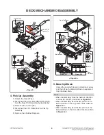
5. Base Up/Down
Unlock the Locking Tab (L2) in direction of arrow
and then lift up the Base Up/Down to separate it
from the Base Main.
Note
•
When reassembling move the Guide in direction
of arrow (A) until it is positioned as
Figure G-1
.
•
When reassembling insert the (B) portion of the
Base Up/Down in the (C) portion of the Guide as
Figure G-2
.
•
When reassembling insert the (D) portion of the
Base Up/Down in the Hole (H2) of the Base Main
as
Figure G-3
.
3
2
1
(L2)
Base Up/Down
Figure G-2
Figure G-1
(C)
(B)
Guide
Base
Up/Down
Base Main
< Figure G >
(B)
(H2)
(A)
Figure G-3
(D)
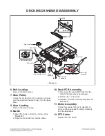
4. Pick Up Assembly
1) Detach the Gasket Tape.
2) Disconnect the wires (BLK, RED, BRN, ORN)
from the Deck PCB Assembly by desoldering.
3) Remove the 4 screws (S2).
4) Disconnect the FFC Cable from the Pick Up
Assembly.
5) Remove the 4 Rubber Dampers.
3
4
(S2)
FFC Cable
Rubber
Damper
Pick Up
Assembly
< Bottom side view >
< Figure F >
5
BLK
RED
BRN
ORN
RED
BK
1
Gasket Tape
Deck PCB
Assembly
2
Содержание CM4550
Страница 13: ...2 2 ...
Страница 17: ...A60 4 SPEAKER SECTION 4 1 FRONT SPEAKER CMS4550F ...
Страница 18: ...2 9 A90 4 2 SUBWOOFER SPEAKER CMS4550W ...
Страница 19: ...2 10 ...
Страница 50: ...4 USB 13 USB_5 V D D 14 3 31 IC501 PIN A8 IC501 PIN A7 ...
Страница 51: ...3 32 ...
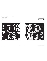
Страница 66: ...3 61 3 62 2 MAIN P C BOARD TOP VIEW BOTTOM VIEW ...
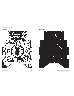
Страница 67: ...3 63 3 64 3 FRONT P C BOARD TOP VIEW BOTTOM VIEW ...

