background image

- 6 -

LGE Internal Use Only

Copyright©2007 LG Electronics. Inc. All right reserved. 
Only for training and service purposes

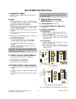
ADJUSTMENT INSTRUCTIONS

1. Application Object

These instructions are applied to all of the 50” PLASMA TV,
PD73A Chassis.

2. Note

(1) Because this is not a hot chassis, it is not necessary to use

an  isolation  transformer.  However,  the  use  of  isolation
transformer will help protect test instrument.

(2) Adjustment must be done in the correct order.
(3) The adjustment must be performed in the circumstance of

25±5°C  of  temperature  and  65±10%  of  relative  humidity  if
there is no specific designation.

(4)  The  input  voltage  of  the  receiver  must  keep  100-240V~,

50/60Hz.

(5) The receiver must be operated for about 15 minutes prior

to the adjustment.

O

After  RGB  Full  white  HEAT-RUN  Mode,  the  receiver  must

be operated prior to adjustment.

O

Enter into HEAT-RUN MODE

1) Press the POWER ON KEY on R/C for adjustment.
2) OSD display and screen display PATTERN MODE.

* Set is activated HEAT-RUN without signal generator in

this mode.

* Single color pattern(RED/BLUE/GREEN) of HEAT-RUN 

mode uses to check PANEL.

3. Chancel memory Setting Method

: You can set channel memory by R/C for adjustment.

1) Press ADJ key on R/C for adjustment.
2) Press ENTER key on “System Control3”.
3) Press VOL + key on “Channel Recover”.

4. PCMCIA CARD Checking Method

: You must adjust DTV 29 Channel and insert PCMCIA CARD

to socket.

1)  If  PCMCIA  CARD  works  normally,  normal  signals  display

on screen.
But it works abnormally, “No CA module” words display on
screen.

5. POWER PCB Assy Voltage

Adjustments 

(Va, Vs Voltage adjustments)

5-1. Test Equipment :

D.M.M. 1EA

5-2.Connection Diagram for Measuring

: refer to Fig.1

5-3. Adjustment Method

(1) Va Adjustment

1) After receiving 100% Full White Pattern, HEAT RUN.
2) C terminal of D.M.M to Va pin of P12, connect -

terminal to GND pin of P12.

3)  After  turning  VR901,  voltage  of  D.M.M  adjustment  as

same  as  Va  voltage  which  on  label  of  panel  right/top.
(Deviation; ±0.5V)

(2) Vs Adjustment

1) C terminal of D.M.M to Vs pin of P12, connect –

terminal to GND pin of P12.

2)  After  turning  VR951,  voltage  of  D.M.M  adjustment  as

same  as  Va  voltage  which  on  label  of  panel  right/top.
(Deviation; ±0.5V)

If you turn on a still screen more than 20 minutes (Especially
Digital pattern, Cross Hatch Pattern), an afterimage may occur
in the black level part of the screen.

Each PCB assembly must be checked by check JIG set.
(Because power PCB Assembly damages to PDP Module,
especially be careful)

(Fig. 1) Connection diagram of power adjustment for measuring

<50” EAY32929001 only for 50PB56>

<50” 6709900020A>

Содержание 42PC56

Страница 1: ...PLASMA TV SERVICE MANUAL CAUTION BEFORE SERVICING THE CHASSIS READ THE SAFETY PRECAUTIONS IN THIS MANUAL CHASSIS PD73A MODEL 50PC55 50PC55 ZB website http biz LGservice com Internal Use Only ...

Страница 2: ...erved Only for training and service purposes CONTENTS SAFETY PRECAUTIONS 3 SPECIFICATIONS 4 ADJUSTMENT INSTRUCTIONS 6 TROUBLE SHOOTING GUIDE 19 BLOCK DIAGRAM 29 EXPLODED VIEW 30 EXPLODED VIEW PARTS LIST 31 REPLACEMENT PARTS LIST 32 SCHEMATIC DIAGRAM PRINTED CIRCUIT DIAGRAM ...

Страница 3: ...by it s Neck Leakage Current Cold Check Antenna Cold Check With the instrument AC plug removed from AC source connect an electrical jumper across the two AC plug prongs Place the AC switch in the on position connect one lead of ohm meter to the AC plug prongs tied together and touch other ohm meter lead in turn to each exposed metallic parts such as antenna terminals phone jacks etc If the exposed...

Страница 4: ... followed 2 Demanded other specification Safety CE IEC specification EMC CE IEC V General Specification 1 Module Specification 50 WXGA MODULE Display Screen Device Aspect Ratio PDP Module Operating Environment Storage Environment Input Voltage 1 2 3 4 5 6 No Item Specification Remark 50 Wide Color Display Module 16 9 PDP50X4A RGB Closed Type Film Filter 1 Temp 0 40deg 2 Humidity 20 80 3 Temp 20 60...

Страница 5: ... 3 4 5 6 7 8 9 10 No Item Specification Remark UK German Italy France Sweden Finland Spain Netherlands Belgium Luxemburg Greece Denmark Czech Austria Poland Portugal Norway Rumania Hungary Bulgaria Croatia Serbia Swiss Slovenia Russia 1 PAL BG 2 PAL DK 3 PAL I I 4 DVB T ID TV 5 SECAM L L Analog Upper Heterodyne Digital COFDM PAL SECAM PAL SECAM NTSC PAL SECAM NTSC Y Cb Cr Y Pb Pr RGB PC HDMI DTV S...

Страница 6: ... Press ADJ key on R C for adjustment 2 Press ENTER key on System Control3 3 Press VOL key on Channel Recover 4 PCMCIA CARD Checking Method You must adjust DTV 29 Channel and insert PCMCIA CARD to socket 1 If PCMCIA CARD works normally normal signals display on screen But it works abnormally No CA module words display on screen 5 POWER PCB Assy Voltage Adjustments Va Vs Voltage adjustments 5 1 Test...

Страница 7: ...3 Preparation for Adjustment 1 As above Fig 2 Connect the Set EDID Download Jig PC Cable 2 Turn on the PC EDID Download Jig And Execute the S W EDID TESTER Ver 2 5 3 Set up S W option Repeat Number 5 Device Address A0 PageByte 8 4 Power on the Set 6 4 Sequence of Adjustment EDID Download 1 Init the data 2 Load the EDID data Open File Analog file for RGB Digital file for HDMI 3 Set the S W as below...

Страница 8: ... B19C B39C 5FC3 61C3 63C3 Hex 9CB1 9CB3 C35F C361 C363 40013 40015 50015 50017 50019 Model Name 42PC55 ZB 42PC56 ZD 50PC55 ZB 50PC56 ZD 50PB56 ZA Hex Data 00 00 00 FC 00 34 32 50 43 35 35 2D 5A 42 0A 20 20 20 00 00 00 FC 00 34 32 50 43 35 36 2D 5A 44 0A 20 20 20 00 00 00 FC 00 35 30 50 43 35 35 2D 5A 42 0A 20 20 20 00 00 00 FC 00 35 30 50 43 35 36 2D 5A 44 0A 20 20 20 00 00 00 FC 00 35 30 50 42 36...

Страница 9: ... Component 720p 50Hz 7 Color Bar MSPG 925FS model 215 pattern 65 signal into Component 2 Set the PSM to Dynamic mode in the Picture menu 3 Press IN STAR key on R C for adjustment 4 Press the G Vol key operate to set then it becomes automatically 5 Auto RGB OK means completed adjustment 10 Adjustment of RGB 10 1 Requirement V This AV color balance adjustment should be performed before white Balance...

Страница 10: ...ost PC Baud Rate 115200bps Download Cortez 2 Zero Calibrate CA 100 and stick the sensor to the center of PDP module surface when you adjust 3 Double click In start key on Controlling R C and get in white balance 4 Set test pattern on and display inside pattern Control is carried out on three color temperature COOL MEDIUM WARM Control is carried out three times 5 When the R G B GAIN is 80 on OSD it...

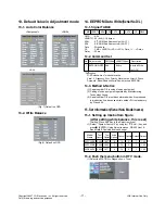
Страница 11: ... Manufacturing Technology Group 3 Serial number D L must be conformed when it is produced in production line because serial number D L is mandatory by D book 4 0 15 Set Information Serial No Model name 15 1 Setting up like bottom figure After setting white balance this is set Setting Press ADJ Key in the Adjust remocon 1 Select System Control 2 by using D E CH key and press V ENTER Using Adjust re...

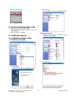
Страница 12: ...e Shipping area 3 The work is finished Push V Key 17 CORTEZ Download 17 1 CORTEZ Download By LGIDS 1 Installation of the LGIDS 1 Extract to folder IDS_Setup ZIP 2 Install LGIDS 1 1 After Click the NEXT icon Installation is finished 3 Install LGIDS 2 1 You can find the ICON on C Program Files LGIDS 2 Download hex file 1 Prepare a Batch File txt RAM File hex on C Program Files LGIDS files In the TEX...

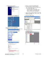
Страница 13: ...e Control case 2 Press the ADJ button 1 Press the System Control 2 menu 2 Enter the GProbe on the RS 232Host menu 3 Enter 115200bps on the Baud Rate menu 4 Enter the Cortez on the Download menu If you don t have a Adjustment Remote Control Menu button on the Remote Control Menu button on the Local Key during 7 8sec After Change a mode you can see GPROBE MODE 5 Execute the LGIDS Program 2 1 Open a ...

Страница 14: ... reserved Only for training and service purposes 17 2 CORTEZ Download By GProbe 5 1 Installation of the GProbe 5 1 Extract to folder GProbe5 0 0 15_S0006_EXE_09A ZIP 2 Install GProbe5 0 0 15 EXE 1 3 Install GProbe5 0 0 15 EXE 2 4 Install GProbe5 0 0 15 EXE 3 CLICK CLICK ...

Страница 15: ...cable 3 SVC MENU Setting for CORTEZ DOWNLOAD case 1 Press the tilt button on the Adjustment Remote Control case 2 Press the ADJ button 1 Press the System Control 2 menu 2 Enter the GProbe on the RS 232Host menu 3 Enter 115200bps on the Baud Rate menu 4 Enter the Cortez on the Download menu If you don t have a Adjustment Remote Control Menu button on the Remote Control Menu button on the Local Key ...

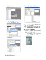
Страница 16: ...1 Turn off the TV after download Turn on 18 Insert the TOOL OPTION SERIAL NUMBER V When you change a Main Ass y you should insert the TV SET s original Serial Number MODEL NAME It is the way how to insert original number 18 1 Insert the Tool Option 1 Insert 2048 on Tool Option1 1697 on Tool Option2 for 42PC55 ZB Press the ENTER Button 2 Insert 2052 on Tool Option1 1953 on Tool Option2 for 50PC55 Z...

Страница 17: ...Term 1 Extract to folder lgterm zip 2 Download biz file using LG Term 1 Prepare the biz that you want to download on ST 2 Connect TV set and PC by using RS232 cable Turn on the TV 3 SVC MENU Setting case1 Press the Turbo Sound button on the Adjustment Remote Control case 2 Press the ADJ button 1 Press the System Control 2 menu 2 Enter the GProbe on the RS 232 Host 3 Enter 115200bps on the Baud Rat...

Страница 18: ...ase Send the file appears Press ctrl s 9 Download takes 60sec 120sec 10 The End of DOWNLOAD 1 After Download successfully you can see EW EW EW EW 2 You can remove RS232 Cable and TV Power SET OFF ON 11 Change the mode 1 Press the ADJ button 2 Press the System Control 2 menu 3 Enter the PC on the RS 232 Host 4 Enter 115200bps on the Baud Rate 5 Enter the Cortez on the Download ...

Страница 19: ... 5V Monitor signal appear No 7 Check the VSC Vs ON signal Does the high tension output appear Does the VSC signal Vs ON appear No No Does the high tension output voltage occur When removing the Y B D Module input connector does output voltage drop When the Y Z B D Module input connector does Power Board high tension output voltage drop No No No 9 Check the Power Board Output high tension circuit Y...

Страница 20: ... DIGITAL BOARD PDP MODULE CN1 AC INLET P1 P2 P3 P11 P12 AC NC AC YH396 03V AC Det RL ON STB 5V GND Vs ON 5V Det M5V ON STB 5V GND NC 6V GND 3 4V ON SMW250 013P 19V 19V GND GND 6V GND 3 4V GND 12V GND SMW250 010P 3 4V 3 4V GND GND 6V 6V GND GND 12V 12V GND GND SMW250 012P 5V 5V GND GND YH396 04V Va Va GND GND GND GND NC Vs Vs Vs YH396 10V 1 2 3 4 5 6 7 8 9 10 11 12 13 DESCRIPTION NO ...

Страница 21: ...G DIGITAL BOARD PDP MODULE CN1 AC INLET P1 P2 P3 P11 P12 AC NC AC YH396 03V AC Det RL ON STB 5V GND Vs ON 5V Det M5V ON STB 5V GND NC 6V GND 3 4V ON SMW250 013P 19V 19V GND GND 6V GND 3 4V GND 12V GND SMW250 010P 3 4V 3 4V GND GND 6V 6V GND GND 12V 12V GND GND SMW250 012P 5V 5V GND GND YH396 04V Va Va GND GND GND GND NC Vs Vs Vs YH396 10V 1 2 3 4 5 6 7 8 9 10 11 12 13 DESCRIPTION NO ...

Страница 22: ...gged in Plug in the power cord Yes No Is the Line Filter and Power Board Cable connected Connect the Cable Yes No Is the appropriate Fuse F101 on the Power Board Replace the Fuse Yes No Is the Power Board and 13P of VSC Board Cable connected Connect the Cable Yes No After removing the cables connect them to the Power Board except the SC101 connection cable and change the AC voltage marking to manu...

Страница 23: ... output voltage normal after removing P103 connector of Y B D Is the appropriate Fuse FS101 FS102 on the Y B D normal Replace if open Yes No Yes Yes Replace the Z Board Is the Z Board normal Is the output voltage normal after removing P1 connector of Z B D Is the appropriate Fuse FS1 FS2 on Z B D replace if open Yes No Yes Is the X Board normal Is the output voltage normal after removing P1 2 3 4 ...

Страница 24: ...ormal Is the VAVS on Check the PDP Module Yes No YES Yes Reconnect the LVDS cable in P800 No Is the IC700 FLI8548 Output normal Replace the VSC No NO Replace the Power board Is the Low High output voltage normal except for stand by 5V NO 4 No Raster 1 Symptom 1 No OSD and image occur at screen 2 It maintains the condition where the front LED is green 2 Procedure check ...

Страница 25: ...lay 1 Symptom 1 LED is green 2 The minute discharge is continuously accomplished from the module 2 Procedure check Is the LVDS cable normal Is the VSC Board normal Is the LVDS cable connected Re insert the Cable Yes No No Yes Does the FIL8548 IC IC700 operate Replace the FIL8548 IC IC700 No Is the Ctrl Board of Module normal Replace the Ctrl B D No No Yes Replace the VSC B D Replace the cable Yes ...

Страница 26: ...ay in side S video AV mode Is the Tuner normal Is the CXA2069Q normal Is the Tuner Cable connected Re insert the cable Yes No No Yes Is the FIL8548 normal Replace the Tuner No Are the Input voltage IIC Communication and CVBS output normal Yes Are the Input voltage IIC Communication and HV sync normal No Replace the IC No Are the input voltage IIC Communication and HV sync normal No Block A Replace...

Страница 27: ... G B input and H V Sync of the J1100 normal Check the input source No Is the HDMI002 IC1004 normal Yes Same as Block A Are Input voltage IIC Communication and HV sync normal No Is the Video input of the A V Jack J1200 normal Yes Same as Block A Check the input source No Replace the IC No Is the Video input of the A V Jack J1201 normal Yes Same as Block A Check the input source No Yes Same as Block...

Страница 28: ... HDMI DTV RF Check the signal before CAX2069 refer to circuit diagram No YES YES Is there no sound only for RF Check the Tuner IN OUT No YES YES Is there no sound only for AV component PC Is the output of CXA2069 normal No YES Is the IC1300 operating normally Replace the IC1300 MSP4450 No Is the IC1301 operating normally Replace the IC1300 STA335BW No YES Replace the VSC B D YES No Replace the CXA...

Страница 29: ... 29 LGE Internal Use Only Copyright 2007 LG Electronics Inc All right reserved Only for training and service purposes BLOCK DIAGRAM Integration ...

Страница 30: ...t 2007 LG Electronics Inc All right reserved Only for training and service purposes EXPLODED VIEW 300 306 400 900 501 590 520 502 303 207 302 101 301 570 204 250 208 203 580 205 200 560 120 202 304 201 240 901 206 600 603 601 602 A2 A21 ...

Страница 31: ...SY FOR PHANTOM LGEMA ASSY 303 AJJ31592705 Supporter Assembly 50PC5 SUPPORTER RIGHT ASSY FOR PHANTOM LGEMA ASSY 304 AJJ31592805 Supporter Assembly 50PC5 SUPPORTER LEFT ASSY FOR PHANTOM LGEMA ASSY 306 ABA31592903 Bracket Assembly DECO 50PC51 ZB 50PC55 ZB NON DECO BRACKET ASSY Direct Grill LGEMA 2ton 400 ACQ31591305 Cover Assembly 50PC5R ZB NON 50 PCM SECD 0 5t FOR LGEMA local 501 AGU31681116 Plate A...

Страница 32: ...X7R C1134 0CK104BF56A C1005X7R104KET 100nF 10 16V X7R C1135 0CK225DFK4A C2012Y5V1C225MT 2 2uF 20 16V Y5V C1135 0CK104CK56A 0603B104K500CT 100nF 10 50V X7R C1136 0CK104CK56A 0603B104K500CT 100nF 10 50V X7R C114 0CK104CF56A 0603B104K160CT 100nF 10 16V X7R C115 0CK104CF56A 0603B104K160CT 100nF 10 16V X7R C116 0CK104CF56A 0603B104K160CT 100nF 10 16V X7R C117 0CK104CF56A 0603B104K160CT 100nF 10 16V X7R...

Страница 33: ...V X7R C1366 0CK104CK56A 0603B104K500CT 100nF 10 50V X7R C1367 0CK104CK56A 0603B104K500CT 100nF 10 50V X7R C1368 0CK104CK56A 0603B104K500CT 100nF 10 50V X7R C1369 0CK104CK56A 0603B104K500CT 100nF 10 50V X7R C137 0CK104CF56A 0603B104K160CT 100nF 10 16V X7R C1370 0CK474EK66A C3216X7R1H474MT 470nF 20 50V X7R C1371 0CK474EK66A C3216X7R1H474MT 470nF 20 50V X7R C1373 0CK104CK56A 0603B104K500CT 100nF 10 5...

Страница 34: ... 50V C0G C196 0CC100CK41A C1608C0G1H100JT 10pF 5 50V C0G C197 0CK475CC94A C1608Y5V0J475ZT 4 7uF 20TO 80 6 C198 0CK475CC94A C1608Y5V0J475ZT 4 7uF 20TO 80 6 C199 0CK104CF56A 0603B104K160CT 100nF 10 16V X7R C200 0CK103CK56A 0603B103K500CT 10nF 10 50V X7R C201 0CC470CK41A C1608C0G1H470JT 47pF 5 50V C0G C202 0CC101CK41A C1608C0G1H101JT 100pF 5 50V C0G C203 0CK104CF56A 0603B104K160CT 100nF 10 16V X7R C2...

Страница 35: ...16V X7R C603 0CK103CK56A 0603B103K500CT 10nF 10 50V X7R C604 0CC100CK41A C1608C0G1H100JT 10pF 5 50V C0G C605 0CK104CF56A 0603B104K160CT 100nF 10 16V X7R C606 0CK104CF56A 0603B104K160CT 100nF 10 16V X7R C608 0CC101CK41A C1608C0G1H101JT 100pF 5 50V C0G C609 0CK104CF56A 0603B104K160CT 100nF 10 16V X7R C610 0CC271CK41A C1608C0G1H271JT 270pF 5 50V C0G C611 0CE107WF6DC MVK6 3TP16VC100M 100uF 20 16V 11 C...

Страница 36: ...50V X7R C787 0CK104CK56A 0603B104K500CT 100nF 10 50V X7R C788 0CK104CK56A 0603B104K500CT 100nF 10 50V X7R C789 0CK104CK56A 0603B104K500CT 100nF 10 50V X7R C790 0CK104CK56A 0603B104K500CT 100nF 10 50V X7R C791 0CK104BF56A C1005X7R104KET 100nF 10 16V X7R C792 0CK104CK56A 0603B104K500CT 100nF 10 50V X7R C793 0CE226WF6DC MVK5 0TP16VC22M 22uF 20 16V 30MA C794 0CK103CK56A 0603B103K500CT 10nF 10 50V X7R ...

Страница 37: ...1 9A 1W S D1000 0DD184009AA KDS184 KDS184 TP KEC 85V D1001 0DD184009AA KDS184 KDS184 TP KEC 85V D101 EAH33946001 CDS3C05GTA 5 6V 6 4V 19V 1 9A 1W D102 EAH33946001 CDS3C05GTA 5 6V 6 4V 19V 1 9A 1W D103 EAH33945901 CDS3C30GTH 30V 50V 120V 1 9A 1W S D104 EAH33945901 CDS3C30GTH 30V 50V 120V 1 9A 1W S D401 0DD100009AM EU1ZV 1 200V 2 5V 10UA 15A 400NS D900 0DS226009AA KDS226 1 2V 85V 300MA 2A 4NSEC 15 D...

Страница 38: ...121JT H 1mm 120OHM 2X1 L1114 6210TCE001P Filter HB 1S2012 121JT H 1mm 120OHM 2X1 L1115 6210TCE001P Filter HB 1S2012 121JT H 1mm 120OHM 2X1 L1116 6210TCE001P Filter HB 1S2012 121JT H 1mm 120OHM 2X1 L1117 6210TCE001G Filter HH 1M3216 501JT 500OHM 3 2X1 6X1 L1206 6210TCE001Z Filter HH 1M2012 600JT 60OHM 2X1 25X1MM L1207 6210TCE001Z Filter HH 1M2012 600JT 60OHM 2X1 25X1MM L1208 6210TCE001Z Filter HH 1...

Страница 39: ...V 50V Q608 0TR387500AA 2SC3875S ALY NPN 5V 60V 50V 150M Q609 0TR150400BA 2SA1504S ASY PNP 5V 50V 50V Q900 0TR387500AA 2SC3875S ALY NPN 5V 60V 50V 150M Q901 0TR387500AA 2SC3875S ALY NPN 5V 60V 50V 150M Q902 0TR387500AA 2SC3875S ALY NPN 5V 60V 50V 150M Q903 0TR387500AA 2SC3875S ALY NPN 5V 60V 50V 150M Q904 0TR387500AA 2SC3875S ALY NPN 5V 60V 50V 150M Q905 0TR387500AA 2SC3875S ALY NPN 5V 60V 50V 150M...

Страница 40: ...RJ0000D677 MCR03EZPJ000 0OHM 5 1 10W 1608 R R107 0RD1101Q609 RDM94T1J1K10 1 1KOHM 5 1 4W 3 2X R107 0RJ0752D677 MCR03EZPJ750 75OHM 5 1 10W 1608 R108 0RD1100Q609 RDM94T1J110R 110OHM 5 1 4W 3 2X1 R108 0RJ0000D677 MCR03EZPJ000 0OHM 5 1 10W 1608 R R109 0RJ0752D677 MCR03EZPJ750 75OHM 5 1 10W 1608 R110 0RJ0000D677 MCR03EZPJ000 0OHM 5 1 10W 1608 R R110 0RJ1002D677 MCR03EZPJ103 10KOHM 5 1 10W 1608 R1101 0R...

Страница 41: ...608 R1243 0RJ0752D677 MCR03EZPJ750 75OHM 5 1 10W 1608 R1244 0RJ0752D677 MCR03EZPJ750 75OHM 5 1 10W 1608 R1245 0RJ0752D677 MCR03EZPJ750 75OHM 5 1 10W 1608 R125 0RJ0472D677 MCR03EZPJ470 47OHM 5 1 10W 1608 R1259 0RJ1001D677 MCR03EZPJ102 1KOHM 5 1 10W 1608 R126 0RJ0472D677 MCR03EZPJ470 47OHM 5 1 10W 1608 R1260 0RJ2001D677 MCR03EZPJ202 2KOHM 5 1 10W 1608 R1261 0RJ2001D677 MCR03EZPJ202 2KOHM 5 1 10W 160...

Страница 42: ...08 0RJ0000D677 MCR03EZPJ000 0OHM 5 1 10W 1608 R R1409 0RJ1500D677 MCR03EZPJ151 150OHM 5 1 10W 1608 R1410 0RJ0000D677 MCR03EZPJ000 0OHM 5 1 10W 1608 R R1411 0RJ2200D677 MCR03EZPJ221 220OHM 5 1 10W 1608 R1412 0RJ2200D677 MCR03EZPJ221 220OHM 5 1 10W 1608 R1413 0RJ0000D677 MCR03EZPJ000 0OHM 5 1 10W 1608 R R1414 0RJ1000D677 MCR03EZPJ101 100OHM 5 1 10W 1608 R1415 0RJ2200D677 MCR03EZPJ221 220OHM 5 1 10W ...

Страница 43: ... R1744 0RJ1500D477 MCR03EZPF151 150OHM 1 1 10W 1608 R1745 0RJ0222D677 MCR03EZPJ220 22OHM 5 1 10W 1608 R1747 0RJ1000D677 MCR03EZPJ101 100OHM 5 1 10W 1608 R1748 0RJ1000D677 MCR03EZPJ101 100OHM 5 1 10W 1608 R1749 0RJ1000D677 MCR03EZPJ101 100OHM 5 1 10W 1608 R175 0RJ1002D677 MCR03EZPJ103 10KOHM 5 1 10W 1608 R1750 0RJ0222C678 MCR01MZPJ220 22OHM 5 1 16W 1005 R1751 0RJ0222C678 MCR01MZPJ220 22OHM 5 1 16W ...

Страница 44: ...1608 R301 0RJ0472D677 MCR03EZPJ470 47OHM 5 1 10W 1608 R302 0RJ1002D677 MCR03EZPJ103 10KOHM 5 1 10W 1608 R303 0RJ1002D677 MCR03EZPJ103 10KOHM 5 1 10W 1608 R304 0RJ1002D677 MCR03EZPJ103 10KOHM 5 1 10W 1608 R305 0RJ1002D677 MCR03EZPJ103 10KOHM 5 1 10W 1608 R306 0RJ1002D677 MCR03EZPJ103 10KOHM 5 1 10W 1608 R309 0RJ0472D677 MCR03EZPJ470 47OHM 5 1 10W 1608 R310 0RJ0472D677 MCR03EZPJ470 47OHM 5 1 10W 160...

Страница 45: ...W 1608 R657 0RJ0102D677 MCR03EZPJ100 10OHM 5 1 10W 1608 R658 0RJ2201D677 MCR03EZPJ222 2 2KOHM 5 1 10W 160 R659 0RJ0000D677 MCR03EZPJ000 0OHM 5 1 10W 1608 R R662 0RH0000D622 MCR10EZHJ000 0OHM 5 1 8W 2012 R R663 0RH0000D622 MCR10EZHJ000 0OHM 5 1 8W 2012 R R664 0RH0000D622 MCR10EZHJ000 0OHM 5 1 8W 2012 R R665 0RH0000D622 MCR10EZHJ000 0OHM 5 1 8W 2012 R R666 0RH0000D622 MCR10EZHJ000 0OHM 5 1 8W 2012 R...

Страница 46: ...R813 0RJ0222C678 MCR01MZPJ220 22OHM 5 1 16W 1005 R816 0RJ0000D677 MCR03EZPJ000 0OHM 5 1 10W 1608 R R821 0RJ0682C678 MCR01MZPJ680 68OHM 5 1 16W 1005 R822 0RJ0000D677 MCR03EZPJ000 0OHM 5 1 10W 1608 R R823 0RJ1500C678 MCR01MZPJ151 150OHM 5 1 16W 1005 R826 0RJ0000D677 MCR03EZPJ000 0OHM 5 1 10W 1608 R R827 0RJ0682C678 MCR01MZPJ680 68OHM 5 1 16W 1005 R829 0RJ0000D677 MCR03EZPJ000 0OHM 5 1 10W 1608 R R84...

Страница 47: ... 5MM 11 5MM 1RX1C JK 6612BBBHN4D TOTX177 3P TX 2 54MM ANGLE 15MBPS JK100 6612J10033A PMJ016 13 13P DIN RCA 14MM ANGLE SW100 EBF32593901 TMUE312GAB 1C1P 12VDC 0 5A VERTIC SW101 140 313B KPT 1115AM 1C1P 12VDC 0 05A HORIZ SW102 140 313B KPT 1115AM 1C1P 12VDC 0 05A HORIZ SW103 140 313B KPT 1115AM 1C1P 12VDC 0 05A HORIZ SW104 140 313B KPT 1115AM 1C1P 12VDC 0 05A HORIZ SW105 140 313B KPT 1115AM 1C1P 12V...

Страница 48: ...SLAVE_SDA V25 JTAG_BS_EN AC20 2 7K FOR LCD R1722 1 CEC_0 22 R1745 22 R723 Vbr_A Vbr_B_1 33 R790 33 R770 20pF C725 M2404HEPROM IC702 3 A2 2 A1 4 VSS 1 A0 5 SDA 6 SCL 7 WP 8 VCC TMUE312GAB SW700 1 2 4 3 5 SYNC_DE HP_DET_S W_0 100 R703 HP_DET_S W_1 EYE 100 R1784 390 R726 Vbr_B_1 FOR LCD 1 2K R1754 5000 1 FOR LCD 4 7uF C1704 1 4 7uF C748 1 200 R1754 1 200 R726 1 FSDATAU 2 FSDATA 0 FSCKEU OCMADDR 20 OC...

Страница 49: ... VCC 74LVC541A PW BUFFER IC302 3 A1 2 A0 4 A2 1 OE1 6 A4 5 A3 7 A5 8 A6 9 A7 10 GND 11 Y7 12 Y6 13 Y5 14 Y4 15 Y3 16 Y2 17 Y1 18 Y0 19 OE2 20 VCC TS_DATA 3 001 K7 003 C8 003 E3 TS_DATA 2 001 K7 003 C8 003 E3 TS_DATA 0 001 K7 003 C8 003 E3 TS_DATA 5 001 K6 003 C8 003 E3 TS_DATA 4 001 K6 003 C8 003 E3 TS_DATA 7 001 K6 003 C8 003 E3 TS_DATA 1 001 K7 003 C8 003 E3 TS_DATA 6 001 K6 003 C8 003 E3 TS_SEL...

Страница 50: ...M 19 NC 18 VDD_2 51 UDQS 52 VSSQ_3 53 NC_6 54 DQ8 55 VDDQ_4 56 DQ9 57 DQ10 58 VSSQ_4 59 DQ11 60 DQ12 61 VDDQ_5 62 DQ13 63 DQ14 64 VSSQ_5 65 DQ15 66 VSS_3 V_TERMINATION 68 R821 68 R827 150 R823 1 DDRCLK_150ohm 68 R897 FOR FULL_HD 68 R898 FOR FULL_HD PANEL_CTL DISP_EN_1 SCL_1 SDA_1 TP806 TP805 68 AR807 68 AR806 68 AR802 68 AR800 68 AR804 68 AR805 68 AR810 68 AR809 68 AR801 68 AR803 68 AR808 SI4925BD...

Страница 51: ...504S Q602 2SC3875S Q603 USE FOR SECAME B C 220 R647 0 1uF C609 2SC3875S Q604 E B C 100 R650 82 R639 SIF 100pF C601 4 7K R636 470 R637 0 R651 R641 READY 1 8VA_FE LEMC3225T 6R8M L605 0 1uF C625 1 8V 1 8VA_FE 0 1uF C606 0 1uF C605 100K R627 100 R629 100 R625 100 R624 47pF C623 DTV_TU_I2C 0 1uF C627 I2C_SDA1 FE_SCL TUNER_RESET FE_RESET 3V3 47pF C624 DTV_TU_I2C I2C_SCL1 0 1uF C626 FE_SDA FE_SDA TUNER_R...

Страница 52: ...LGE Internal Use Only Copyright 2007 LG Electronics Inc All right reserved Only for training and service purposes MAIN TOP MAIN BOTTOM CONTROL B D SIDE A V IR LED PRINTED CIRCUIT BOARD ...

Страница 53: ...Sep 2007 Printed in Korea P NO MFL38562706 ...

Отзывы: