background image

ipLDK-60 Hardware Description and Installation Manual 

Issue 2 

INTRODUCTION  

July, 2010 


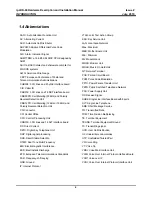
1.4 Abbreviations 


AAFU: Auto Attendant Function Unit 

AC: Alternating Current  

ACD: Automatic Call Distributor 

ADPCM: Adaptive Differential Pulse Code 

Modulation 

AIS : Alarm Indication Signal 

ARM7TDMI: a 16-bit/32-bit RISC CPU designed by 

ARM 

ASIC: a BASIC dialect and shareware compiler for 

MS-DOS systems 

AWG: American Wire Gauge 

CEPT: European Conference of Postal and 

Telecommunications Administrations 

CHB308: 3 CO lines and 8 hybrid interface board 

CID: Caller ID 

CKB316: 3 CO lines and 16 DKT interface board 

CMU50PR: Call Metering (50KHz) and Polarity 

Reversal Detection Unit 

CMU12PR: Call Metering (12KHz or 16KHz) and 

Polarity Reversal Detection Unit 

CN: Connector 

CO: Central Office 

CPU: Central Processing Unit 

CSB316: 3 CO lines and 16 SLT interface board 

DC: Direct Current 

DKTU: Digital Key Telephone Unit 

DSP: Digital signal processing 

DSS: Direct Station Selection 

DTMF: Dual Tone Multi Frequency 

EMI: Electromagnetic Interference 

ESD: Electrostatic Discharge 

ETS: European Telecommunications Standards 

FSK: Frequency-shift keying 

GND: Ground 

IP: Internet Protocol 

JTAG: Joint Test Action Group 

KSU: Key Service Unit 

LAN: Local Area Network 

Max.: Maximum 

MBU: Mother Board Unit 

Min.: Minimum 

MJ: Modular Jack 

MODU: Modem Unit 

MOHU: Music On Hold Unit 

NT: Network Terminal 

PCB: Printed Circuit Board 

PCM: Pulse Code Modulation 

PFTU: Power Failure Transfer Unit 

PSTN: Public Switched Telephone Network 

PSU: Power Supply Unit 

RX: Receive Signal 

SLIB8: Single Line Interface Board with 8ports 

SLT: Single Line Telephone 

SMS: Short Message Service 

TD: Transmitted Data 

TDM: Time Division Multiplexing 

TE: Terminal Equipment 

TEGND: Terminal Equipment Ground 

TX: Transmitting signal 

UCD: User Call Distribution 

UL: Underwriters Laboratories 

UTP: Unshielded Twisted Pair 

VR: Voice Ring 

VT: Voice Tip 

VMIU: Voice Mail Interface Unit 

VOIB: Voice Over Internet Protocol interface Board 

VOIP: Voice over IP 

VOIU: Voice Over Internet Protocol Interface Unit 


Содержание ipldk-60

Страница 1: ...Hardware Description and Installation Manual ...

Страница 2: ...ected If this is not done the telephone company may temporarily disconnect service The local telephone company may make changes in its communications facilities or procedures If these changes could reasonably be expected to affect the use of the ipLDK 60 or compatibility with the network the telephone company is required to give advanced written notice to the user allowing the user to take appropr...

Страница 3: ...odifications in construction of this device which are not expressly approved by the party responsible for compliance could void the user s authority to operate the equipment RF Exposure Statement This equipment complies with FCC IC RF radiation exposure limits set forth for an uncontrolled environment Use of other accessories may not ensure compliance with FCC IC RF exposure guidelines This device...

Страница 4: ... Manual Issue 2 July 2010 iii Revision History ISSUE DATE Contents of Changes 1 0 2007 01 Initial Release 1 1 2009 02 Added PRHB8 2 0 2010 07 Added EMU2 CKB316 LDP 7200 series LIP 7000 8000 series IP phones General edits 2 1 2011 06 Added GDC 600BE ...

Страница 5: ...ystem Capacity 7 2 3 3 Base station specification GDC 400B 600B 600BE 7 2 3 4 Wireless Terminal specification 8 3 KSU INSTALLATION 9 3 1 Pre Installation 9 3 1 1 Safety Installation Instructions 9 3 1 2 Installation precautions 9 3 1 3 Wiring Precautions 9 3 2 KSU Installation 10 3 2 1 Unpacking 10 3 2 2 KSU Exterior and Dimension 11 3 2 3 Opening and Closing the Front Cover 12 3 2 4 Power Supply ...

Страница 6: ...ace Board 44 4 5 5 VOIB Voice over Internet protocol Board 45 4 5 6 E1HB8 E1R2 and 8 Hybrid Interface Board 47 4 5 7 PRHB8 PRI and 8 Hybrid Interface Board 49 4 5 8 PRHB8 T1 PRI Board w T1 for N A Only 51 4 6 Function Board Installation 53 4 6 1 Voice Mail Interface Unit VMIU Auto Attendant Function Unit AAFU 53 4 6 2 VMIB8 Voice Mail Interface Board 8 Hours 54 4 6 3 Modem Function Unit MODU 54 5 ...
Страница 7: ...allation Manual Issue 2 July 2010 v 7 STARTING THE IPLDK 60 71 7 1 Before Starting the ipLDK 60 System 71 7 2 Basic Programming 71 7 2 1 DKT Programming 71 7 2 2 Entering the Programming Mode 73 7 2 3 Pre Programming 73 8 TROUBLESHOOTING 81 ...

Страница 8: ...wer company 9 Do not allow anything to rest on the power cord Do not locate this product where the cord could be abused by people walking on it 9 Do not overload wall outlets and extension cords as this can result in the risk of fire or electric shock 9 Never push objects of any kind into this product through KSU slots or connectors as they may touch dangerous voltage points or short out parts tha...

Страница 9: ...ly and return this system to your dealer 9 To prevent the risk of fire electric shock or energy hazard do not expose this product to rain or any type of moisture 9 To protect PCB from static electricity discharge body static before touching connectors and or components by touching ground or wearing a ground strap WARNING Danger of explosion if battery is not correctly replaced Replace only with th...

Страница 10: ...ystem specifications and capacity Section 3 KSU Installation Describes detailed instructions for planning the installation site and procedures to install the ipLDK 60 System Section 4 Board Installation Describes detailed instructions for installing components of the ipLDK 60 Board Section 5 Terminal Connections and Wiring Method Describes the kinds of terminals maximum distance and other device c...

Страница 11: ...ital signal processing DSS Direct Station Selection DTMF Dual Tone Multi Frequency EMI Electromagnetic Interference ESD Electrostatic Discharge ETS European Telecommunications Standards FSK Frequency shift keying GND Ground IP Internet Protocol JTAG Joint Test Action Group KSU Key Service Unit LAN Local Area Network Max Maximum MBU Mother Board Unit Min Minimum MJ Modular Jack MODU Modem Unit MOHU...

Страница 12: ...clude 9 Flexible architecture 9 Simple system structure 9 Powerful PC application via LAN Modem RS 232C 9 Enhanced voice features 9 Easy installation efficient system management Remote admin software upgrade through LAN connection Remote admin software upgrade through PSTN modem 9 Value Added features Distinctive Voice mail ADPCM 32 Kbps Basic CID CO SLT Function 8 Poly internal MOH 13 Music sourc...

Страница 13: ... Description and Installation Manual Issue 2 SYSTEM OVERVIEW July 2010 3 2 1 1 System Connection Diagram The following Figure shows the components that make up the ipLDK 60 System FIGURE 2 1 1 SYSTEM CONNECTION DIAGRAM ...

Страница 14: ...face Board CMU50PR Call Metering 50Hz and Polarity Reversal Detection Unit 3 channels CMU12PR Call Metering 12KHz or 16KHz and Polarity Reversal Detection Unit 3 channels SLU8 8 SLT Interface Unit Installed on CSB316 as a default SLIB8 8 SLT Interface Board VOIB Voice over IP Board 4ch VOIU Voice over IP unit 4ch E1HB8 E1R2 and 8 Hybrid Interface Board SLU8 8 SLT Interface Unit Installed on E1HB8 ...
Страница 15: ... and 8 Hybrid Interface Board CMU50PR Call Metering 50Hz and Polarity Reversal Detection Unit 3 channels CMU12PR Call Metering 12KHz or 16KHz and Polarity Reversal Detection Unit 3 channels CKB316 3CO Lines and 16 Digital Telephone Interface Board CSB316 3 CO Lines and 16 SLT Interface Board CMU50PR Call Metering 50 Hz and Polarity Reversal Detection Unit 3 channels CMU12PR Call Metering 12KHz or ...

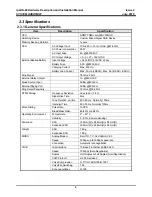
Страница 16: ...0dBm 600ohm External Paging Port 0dBm 600ohm Ring Detect Sensitivity 30Vrms 16 55Hz DTMF Dialing Frequency Deviation Less than 1 8 Signal Rise Time 5ms Tone Duration on time Min 50 ms Normally 100ms Inter digit Time Min 30ms Normally 100ms Pulse Dialing Pulse Rate 10PPS Break Make Ratio 60 40 or 66 33 Operating Environment Temperature 0o 40o C Humidity 0 80 non condensing Dimension KSU 339mm W x 2...

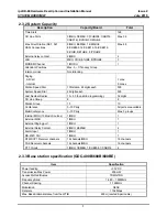
Страница 17: ...digits each 500 Last Number Redial 15 50 by admin programming 32 digits CO Line Group 8 8 Station Group 10 10 Conference 3 15 Party All ports are available Multi Conference 3 15 Party Max 3 groups Internal MOH 13 Music Sources 1 MBU 1 External MOH 1 MBU 1 External Paging port 1 MBU 1 External Relay Contact 2 MBU 2 EMBU 4 Alarm Input 1 MBU 1 RS 232C Port 1 MBU 1 DTMF CPT Receiver channels 16 channe...

Страница 18: ...re Description and Installation Manual Issue 2 SYSTEM OVERVIEW July 2010 8 2 3 4 Wireless Terminal specification Item Specification Max Transmission Power 250mW Modulation Method GFSK Frequency Band 1 880MHz 1 900MHz ...

Страница 19: ...s or vibrations are frequent or strong 9 Dusty places or places where water or oil may be exposed to the System 9 Near radio frequency generating devices such as sewing machines or electric welders 9 On or near computers fax machines or other office equipment as well as microwave ovens or air conditioners 9 Do not obstruct the openings on the sides or top of the ipLDK 60 System 9 Do not stack up t...

Страница 20: ...ption and Installation Manual Issue 2 KSU INSTALLATION July 2010 10 3 2 KSU Installation 3 2 1 Unpacking Open the box and verify that the items shown in Figure 3 2 1 are included with the Basic KSU FIGURE 3 2 1 CARTON CONTENTS ...

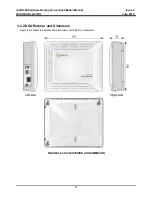
Страница 21: ...Description and Installation Manual Issue 2 KSU INSTALLATION July 2010 11 3 2 2 KSU Exterior and Dimension Figure 3 2 2 shows the exterior and dimensions of the KSU in milli meters FIGURE 3 2 2 KSU EXTERIOR AND DIMENSION ...

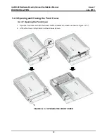
Страница 22: ...ly 2010 12 3 2 3 Opening and Closing the Front Cover 3 2 3 1 Opening the Front Cover 1 Open the Cord cover and turn the screws counter clockwise to loosen as shown in Figure 3 2 3 1 2 Lift the front cover in the direction of the arrow as shown FIGURE 3 2 3 1 OPENING THE FRONT COVER ...

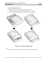
Страница 23: ... the slots of the KSU as shown in Figure 3 2 3 2 2 Then put the front cover down on the KSU in the direction of the arrow as shown 3 Turn the screws clockwise to tighten and close the Wiring Tray cover as in the Figure FIGURE 3 2 3 2 CLOSING THE FRONT COVER Note Prior to operation the front cover of the ipLDK 60 should be closed and the screws tightened ...

Страница 24: ...he KSU and is pre installed in the ipLDK 60 KSU The PSU provides three DC voltage power sources to MBU through the 7 pin connector CN7 Description Specification AC Voltage Input 100 240 VAC 10 AC Frequency 47 63Hz AC Power Consumption 90W AC Input Fuse 2A 250Volt AC DC Output Voltage 5V 3A 5V 0 2A 27V 0 2A 30 1 5A DC Input Voltage 24 Volt DC 12VDC x 2ea Battery Fuse 5 0A 250Volt Battery Charging C...

Страница 25: ...he screw 3 Then connect the grounding wire to an appropriate ground source refer to Caution FIGURE 3 2 5 GROUNDING THE KSU CAUTION 9 The equipment should be connected to a socket outlet with a protective ground connection 9 For ground wire green and yellow insulation is required and using a UL 1015 AWG 18 1 0mm or larger conductor It is recommended that the ground wire is shorter than 1m 3 28ft 9 ...

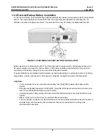
Страница 26: ... battery voltage is too low to maintain full system operation The external batteries can maintain System operation as needed depending on several elements such as battery charge status condition and capacity of the batteries and System configuration number of Station ports CAUTION 9 It is recommended to use an external backup battery fuse 5A 250V between the battery and the System 9 Recommended ba...

Страница 27: ...ting 1 Install three 3 anchor plugs in the wall using the mounting template included for accurate placement Figure 3 2 7 1A 2 Attach the mounting template using the three 3 screws and anchors included 3 Hook the KSU onto the screws making sure that the System slides down securely Figure 3 2 7 1B FIGURE 3 2 7 1A MOUNTING TEMPLATE ...

Страница 28: ...ipLDK 60 Hardware Description and Installation Manual Issue 2 KSU INSTALLATION July 2010 18 FIGURE 3 2 7 1B KSU WALL MOUNTING Note Be careful not to drop the KSU ...

Отзывы: