


Appendix C: Theory of operation
Paper path and transport components
For an image to be printed, the paper or specialty media has to be moved from an input source, such as a tray,
into the printer and eventually exit into an output source.
The most important component in this process is the paper. Old, damaged, or out-of-specification paper can
and will cause feed and transport problems. If you encounter problems, you should always check the paper
first. See
“Paper and specialty media guide” on page 26
. In addition, it is always good practice to check the
printer and driver settings to see if the paper being used matches the user settings. It is not uncommon to find
a user printing on cardstock with the printer programmed to print on a plain paper setting.
The printer feed and transport components can fail and cause paper jams or other feed and transport problems.
These components should be examined for damage or wear and replaced if necessary.
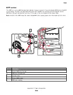
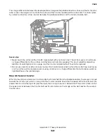
Tray section
Paper size and detection
The paper size is only detected based on the setting of the length guide. The width guides do not provide
paper size information to the printer. The length guide can be adjusted to accommodate different paper sizes
by moving it to the front or rear of the tray. The length guide should come into contact with the paper and hold
it in position. The width guide is designed so that it can adjust to the paper width by moving the guide to the
left or right. Both paper guides can be locked to position.
The sensor (550-sheet tray empty) detects paper and the sensor (550-sheet tray paper size) detects the size
of paper supplied from each tray assembly. A system of four switches is used to decode the paper size, which
is then sent to the controller board.
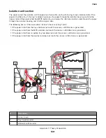
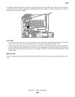
Paper lift
The sensor (pick roller position) determines if the lift plate in the paper tray is at the optimum position for paper
to be properly picked. As paper is fed out, clearance occurs between the paper and the pick rollers. When the
sensor determines the specified amount of clearance, the lift plate is raised to position the paper in the optimum
position to be picked properly.
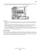
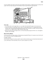
Paper pick
The pick roller assembly is a mechanical unit supplying paper from the tray to the paper path. Three motors
move the paper from the tray to the transfer module at the second transfer station. The motor (isolation) feeds
the paper from the pick system to the alignment rollers. The leading edge of the paper is aligned to the alignment
rollers and then fed into the transfer nip.
The system is timed so that the image is formed and the page is picked to allow the image to be correctly
placed on the paper. The sensor (550-sheet tray empty) detects if there is paper present in the tray. If paper is
present, the media feeder drives the pick roller which moves the paper from the tray to the isolation unit.
7528
Appendix C: Theory of operation
529
Содержание XC4150
Страница 34: ...7528 34 ...
Страница 276: ...7528 276 ...
Страница 294: ...Scan SE Scanner Info 7528 Service menus 294 ...
Страница 310: ...3 Disconnect the front door straps C C 4 Remove the screw C securing the ground cables D 7528 Repair information 310 ...
Страница 317: ...3 Remove the screw B from the lower left side of the cover B 7528 Repair information 317 ...
Страница 320: ...3 Remove the three screws A 7528 Repair information 320 ...
Страница 325: ...4 Remove the six screws B from the bracket and then remove the bracket B 7528 Repair information 325 ...
Страница 327: ...3 Remove the E clip B 4 Remove the E clip C 7528 Repair information 327 ...
Страница 331: ...Top frame cover removal 1 Open the front cover and then raise the diverter 7528 Repair information 331 ...
Страница 352: ...3 Disconnect the motor cable A 4 Remove the three screws B and then remove the motor 7528 Repair information 352 ...
Страница 354: ...4 Disconnect the fuser fan cable A from the controller board A 5 Remove the two screws B 7528 Repair information 354 ...
Страница 358: ...5 Remove the two screws D from under the gear box 7528 Repair information 358 ...
Страница 360: ...3 Disconnect the cable A from the LVPS 7528 Repair information 360 ...
Страница 361: ...4 Remove the seven screws B 5 Disconnect the two cables C and then remove the LVPS 7528 Repair information 361 ...
Страница 364: ...6 Disconnect the black only retract motor cable A 7 Remove the two screws B 7528 Repair information 364 ...
Страница 367: ...6 Pull the mounting assembly away from the printer 7 Disconnect the sensor cable B 7528 Repair information 367 ...
Страница 370: ...3 Disconnect the motor cable A A 7528 Repair information 370 ...
Страница 371: ...4 Remove the four screws B and then remove the motor B 7528 Repair information 371 ...
Страница 374: ...4 Disconnect the cable B 5 Remove the screw C securing the HVPS C 7528 Repair information 374 ...
Страница 377: ...5 Pull the sensor A out of the printer 6 Disconnect the sensor cable B to remove the sensor 7528 Repair information 377 ...
Страница 389: ...5 Remove the imaging kit 1 2 3 6 Open the front cover 7 Remove the transfer module 1 2 7528 Repair information 389 ...
Страница 398: ...9 Remove the bracket D and then unhook the spring E 10 Remove the spacer F 7528 Repair information 398 ...
Страница 400: ...14 Remove the clip M and then remove the spacer 7528 Repair information 400 ...
Страница 403: ...7528 Repair information 403 ...
Страница 414: ...5 Remove the screw C from the printhead 7528 Repair information 414 ...
Страница 417: ...7 Remove the E clip A and then remove the gear 8 Remove the E clip B from inside the frame 7528 Repair information 417 ...
Страница 424: ...3 Remove the three screws A securing the isolation unit 4 Remove the biasing screw B 7528 Repair information 424 ...
Страница 429: ...8 Route the ADF cable through the flatbed 9 Remove the ADF 7528 Repair information 429 ...
Страница 437: ...7 Disconnect the two cables B on the controller board 7528 Repair information 437 ...
Страница 439: ...10 Remove the cotter pin D on the left side of the flatbed 11 Slide out the pins to remove 7528 Repair information 439 ...
Страница 443: ...5 Remove the screw D and then remove the scanner tilt D 7528 Repair information 443 ...
Страница 446: ...5 Remove the two screws B B 6 Disconnect the cable C C 7 Remove the motor 7528 Repair information 446 ...
Страница 450: ...3 Release the latch A and then remove the sensor cover A 4 Release the two latches B B 7528 Repair information 450 ...
Страница 478: ...7528 478 ...
Страница 485: ...7528 485 ...
Страница 487: ...Assembly 1 Covers 1 2 4 6 7 8 9 1 14 10 3 5 13 13 11 11 12 7528 Parts catalog 487 ...
Страница 489: ...Assembly 2 Covers 2 14 7528 Parts catalog 489 ...
Страница 491: ...Assembly 3 Control panel 5 4 3 2 1 7528 Parts catalog 491 ...
Страница 493: ...Assembly 4 ADF and flatbed 1 3 11 10 4 9 5 6 7 8 2 7528 Parts catalog 493 ...
Страница 495: ...Assembly 5 Fuser 1 7528 Parts catalog 495 ...
Страница 497: ...Assembly 6 Transfer module 1 2 7528 Parts catalog 497 ...
Страница 499: ...Assembly 7 Paper feed 8 2 1 2 4 7 3 5 5 6 7528 Parts catalog 499 ...
Страница 501: ...Assembly 8 Paper path 1 8 6 2 3 1 10 5 7 9 4 7528 Parts catalog 501 ...
Страница 503: ...Assembly 9 Paper path 2 1 4 2 5 10 3 6 9 7 8 7528 Parts catalog 503 ...
Страница 505: ...Assembly 10 Duplex 9 8 3 3 7 6 1 1 2 4 5 7528 Parts catalog 505 ...
Страница 507: ...Assembly 11 Electrical 16 2 3 4 5 7 8 9 11 12 13 15 6 1 14 10 7528 Parts catalog 507 ...
Страница 510: ...7528 Parts catalog 510 ...
Страница 511: ...Assembly 12 550 sheet tray option 1 2 1 7528 Parts catalog 511 ...
Страница 513: ...Assembly 13 550 sheet tray option 2 1 2 3 4 12 11 6 13 5 9 10 7 8 7528 Parts catalog 513 ...
Страница 515: ...Assembly 14 Adjustable stand 2 2 3 3 1 7528 Parts catalog 515 ...
Страница 518: ...7528 Parts catalog 518 ...
Страница 520: ...7528 520 ...
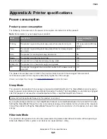
Страница 524: ...Storage temperature and relative humidity 10 to 40 C 14 to 104 F 8 to 80 RH 7528 Appendix A Printer specifications 524 ...
Страница 527: ...3 Apply the changes 7528 Appendix B Options and features 527 ...
Страница 528: ...7528 528 ...
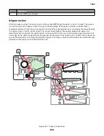
Страница 533: ... Description 1 Transfer belt 2 Sensor input 3 Aligner roller 4 Transfer roller 7528 Appendix C Theory of operation 533 ...
Страница 554: ...7528 554 ...
Страница 568: ...7528 Part number index 568 ...
Страница 574: ...7528 Part name index 574 ...


