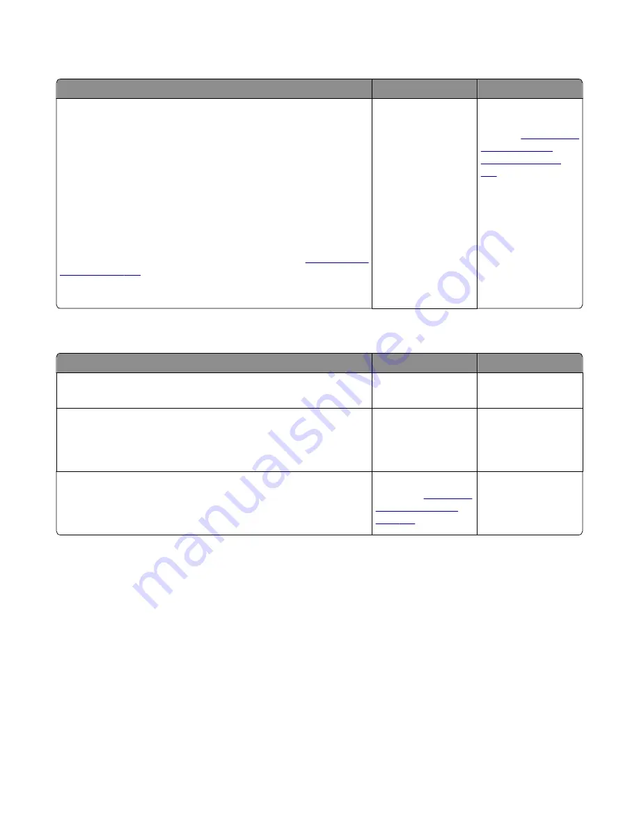
Toner meter cycle (TMC) card service check
Actions
Yes
No
Perform the Base Sensor Test:
a
Enter Diagnostics menu.
Turn the printer on, press and hold
3
and
6
, and release the buttons
with the installed memory and processor speed displays.
b
Select Base Sensor Test, and press
Select
.
c
Select the sensor you want to test, open the toner door, remove the
corresponding toner cartridge, and press
Select
.
d
Note whether the operator panel shows a change in state.
Note:
If the reflective disk is not showing on the cartridge, then rotate
the gear clockwise to expose the reflective surface.
For additional information about the Base Sensor Test, see
Does the operator panel display a change of state?
Replace the toner
cartridge.
Replace the toner
meter cycle (TMC)
card. See
cycle (TMC) card
removal” on page
258
USB service check
Actions
Yes
No
Step 1
Is the USB cable properly connected to the printer and host PC?
Go to step 2.
Properly connect the
cable at both ends.
Step 2
Try a different USB cable.
Does this fix the issue?
Issue fixed.
Go to step 3.
Step 3
Connect a different device to the USB cable.
Did the host PC see the device?
Replace the controller
board. See
.
There is an issue with
the host machine.
Network service check
Note:
Before starting this service check, print out the network setup page. This page is found under
Menu>Reports>Network Settings
. Consult the network administrator to verify that the physical and wireless
network settings displayed on the network settings page for the device are properly configured. If a wireless
network is used, then verify that the printer is in range of the host computer or wireless access point, and there is no
electronic interference. Have the network administrator verify that the device is using the correct SSID, and wireless
security protocols. For more network troubleshooting information, consult the Lexmark Network Setup Guide.
7527
Diagnostic information
137
Содержание XC2132
Страница 18: ...7527 18 ...
Страница 22: ...7527 22 ...
Страница 34: ...7527 34 ...
Страница 54: ...2 Open the top door 7527 Diagnostic information 54 ...
Страница 184: ...7527 184 ...
Страница 226: ...7527 226 ...
Страница 314: ...5 Disconnect the belt C 6 Disconnect the fan and remove 7527 Repair information 314 ...
Страница 317: ...3 Pull out the legs of the exit bail one at a time and lift to remove 7527 Repair information 317 ...
Страница 342: ...Dust cover removal 1 Slightly raise the dust cover 2 Pull the dust cover to remove 7527 Repair information 342 ...
Страница 344: ...Note Feel each rubber surface to verify it turns properly in the direction shown 7527 Repair information 344 ...
Страница 345: ...Component locations Controller board CX310 models 7527 Component locations 345 ...
Страница 346: ...CX410 models 7527 Component locations 346 ...
Страница 352: ...7527 352 ...
Страница 359: ...7527 359 ...
Страница 361: ...Assembly 1 Covers 7527 Parts catalog 361 ...
Страница 363: ...Assembly 2 Scanner 7527 Parts catalog 363 ...
Страница 365: ...Assembly 3 Paperpath 7527 Parts catalog 365 ...
Страница 368: ...7527 Parts catalog 368 ...
Страница 369: ...Assembly 4 Operator panels 7527 Parts catalog 369 ...
Страница 372: ...7527 Parts catalog 372 ...
Страница 373: ...Assembly 5 Electronics 7527 Parts catalog 373 ...
Страница 376: ...7527 Parts catalog 376 ...
Страница 377: ...Assembly 6 Cables and sensors 7527 Parts catalog 377 ...
Страница 379: ...Assembly 7 Media drawers and trays 7527 Parts catalog 379 ...
Страница 382: ...7527 382 ...
Страница 390: ...7527 390 ...
Страница 404: ...7527 404 ...
Страница 422: ...7527 Part number index 422 ...
Страница 428: ...7527 Part name index 428 ...


