2-13
Service Manual
4447-20x
Go Back
Previous
Next
Print quality check
Step
Questions / actions
Yes
No
1
Turn off the printer by unplugging the power cord. Wait
for 10 seconds, and turn on the printer. Run the print job
again.
Does the problem remain?
Go to step 2.
Problem
resolved
2
Run a test print. From the home screen, touch
>
Print Reports
>
Demonstration Page
. Check
if there are any problems on the print out.
Does the problem remain?
Go to step 3.
Problem
resolved
3
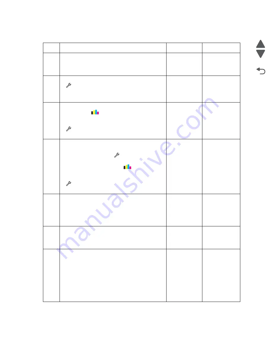
Deep clean or clean the printhead. From the home
screen, touch
>
More Options
>
Deep
Clean
Printhead
>
Deep Clean Color
and Black
.
Run a test print. From the home screen, touch
>
Print Reports
>
Demonstration Page
.
Does the problem remain?
Go to step 4.
Problem
resolved
4
Align the printer. Do either of the following:
• Bring the printer up in Manufacturing mode. From
the home screen, touch
>
Manufacturing
Test
>
Align Printer
.
• From the home scree, touch
>
More
Options
>
Align Printer
.
Run a test print. From the home screen, touch
>
Print Reports
>
Demonstration Page
.
Does the problem remain?
Go to step 5.
Problem
resolved
5
Check the alignment sensor for any contamination and
damage. Clean the alignment sensor with a piece of
cloth. Reseat the alignment sensor cable.
Is the alignment sensor free from contamination and
damage?
Go to step 6.
Replace the
alignment
sensor. See
“Alignment
sensor
removal” on
page 4-57
.
6
Check the encoder strip for any contamination. Clean
the encoder strip with a piece of cloth. See
Does the problem remain?
Go to step 7.
Problem
resolved
7
Check the condition of the carrier assembly. Manually
move the carrier assembly from left to right to see if it
can move easily. Check if the carrier shaft is still in good
condition and does not need regreasing.
Note:
Manually turn the Pressure Release Arm (PRA)
gear clockwise to move the carrier assembly from the
maintenance station. See
carrier assembly lock (without covers)” on
page 3-22
Can the carrier assembly move freely without too
much resistance?
Go to step 8.
Go to step 11.
Содержание Pro5500 Series
Страница 11: ...Safety information xi 4447 20x Go Back Previous Next 012 3456789...
Страница 191: ...Repair information 4 22 4447 20x Go Back Previous Next Disassembly Flow chart This is the photo of the ADF input tray...
Страница 254: ...4 85 Service Manual 4447 20x Go Back Previous Next Disassembly Flow chart...
Страница 260: ...5 6 Service Manual 4447 20x Go Back Previous Next Wireless card Card reader JP3...
Страница 261: ...Connector locations 5 7 4447 20x Go Back Previous Next Carrier card J1 J2 J3...
Страница 262: ...5 8 Service Manual 4447 20x Go Back Previous Next...
Страница 266: ...7 2 Service Manual 4447 20x Go Back Previous Next Assembly 1 Covers 5 6 8 9 10 11 12 13 16 17 1 14 15 7 2 3 4...
Страница 268: ...7 4 Service Manual 4447 20x Go Back Previous Next Assembly 2 Engine 1 2 3 5 4...
Страница 270: ...7 6 Service Manual 4447 20x Go Back Previous Next Assembly 3 Fluid system assembly 1 3 2 5 4...
Страница 274: ...7 10 Service Manual 4447 20x Go Back Previous Next...
Страница 277: ...I 3 Service Manual 4447 20x Go Back Previous Next...


