SURFACE REMOTE TEMPERATURE SENSOR
Cat. No. 23A00-1
Installation Instructions and User’s Guide
INSTALLATION
ENGLISH
DI-021-EM231-00A
DESCRIPTION
The Model 23A00-1 is a surface mount temperature sensor that can be installed on an Omnistat2
thermostat to monitor the temperature of a remote location, can be combined with the onboard
temperature sensor for the average temperature of two locations, or can be used to monitor the
outdoor temperature for dual fuel heat pump installations.
When used indoors, the remote sensor allows a customer to monitor the temperature of an area without having a visible thermostat. The thermostat, or group of thermostats, could
be in a different location offering the customer complete control of temperatures.
INSTALLATION
1. Install Omnistat2 base in selected thermostat location and connect to heating/cooling equipment per manufacturer’s instructions.
2. Connect thermostat to base and confi rm that everything operates correctly. Disconnect the thermostat from the base.
3. Run a twisted pair, shielded cable from the Omnistat2 to the Remote Temperature Sensor location. For distances up to 100 feet, typical twisted pair, PVC-insulated, shielded
cable may be used. For distances from 100-150 feet, twisted pair with polypropylene insulated conductors, shielded must be used. For distances from 150-250 feet, twisted pair
with foam-polyethylene insulated conductors, shielded must be used. Wire runs must not exceed 250 feet.
4. Open cover to the Model 23A00-1 Remote Temperature Sensor. Connect the data wires of the shielded cable to the wires on the temperature sensor using the supplied wire splices.
5. Wrap the shield around the jacket of the cable and tape.
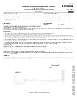
6. At the Omnistat2 location, make the connections to the Green and Black terminals under the section marked “Remote Temp Sensor” on the right terminal strip. Note that the
shield and one of the wires from the remote temperature sensor are tied together and get connected to the Black terminal – See Figure 1.
CONFIGURATION
Reconnect the Omnistat2 to the base and confi gure the remote temperature sensor according to the application.
The Temperature Sensor Installation Settings are used to confi gure the internal temperature sensor and optional remote temperature sensor that is connected to the thermostat.
Any temperature sensors that are set as the same type (i.e. indoor or outdoor) will display the average temperature reading among the sensors. An asterisk (*) next to a setup item
indicates the default setting.
Internal Sensor: This will enable or disable the onboard temperature sensor for indoor use only. *Enabled
External Sensor 1: This will enable the external temperature sensor for indoor or outdoor use. All indoor and outdoor temperatures are averaged between all sensors of the same
type. *Disabled
OPERATION
On the Omnistat2 Home Page, confi rm that the thermostat is displaying the proper temperature. If the remote temperature sensor is confi gured as “outdoor’, confi rm that the proper
outdoor temperature is displayed in the Message Bar on the Omnistat2.
SPECIFICATIONS
DIMENSIONS:
2W x 1.5H x 1D
WARNINGS AND CAUTIONS
• Read and understand all instructions. Follow all warnings and instructions marked on the product.
• Do not use this product near water - e.g., near a tub, wash basin, kitchen sink or laundry tub, in a
wet basement, or near a swimming pool.
• Never push objects of any kind into this product through openings, as they may touch dangerous
voltages.
• SAVE THESE INSTRUCTIONS.
WARNINGS AND CAUTIONS
• Never install communications wiring or components during a lightning storm.
• Never install communications components in wet locations unless the
components are designed specifi cally for use in wet locations.
• Never touch uninsulated wires or terminals unless the wiring has been
disconnected at the network interface.
• Use caution when installing or modifying communications wiring or
components.
(23I00-1)
FIGURE 1: OVERALL INSTALLATION DIAGRAM
WEB
VERSION


