background image


Leonton 

EG5-0501-SFP Series 

(EG5-0501-SFP / EG5-0501-SFP-T) 


User Manual


Содержание EG5-0501-SFP Series

Страница 1: ...Leonton EG5 0501 SFP Series EG5 0501 SFP EG5 0501 SFP T User Manual ...

Страница 2: ...ut not limited to the implied warranties of merchantability and fitness for a particular purpose Leonton Technologies Co Ltd may make improvements and or changes to the product and or specifications of the product described in this manual without prior notice Leonton Technologies Co Ltd will not be liable for any technical inaccuracies or typographical errors found in this guide Changes are period...

Страница 3: ... the equipment off and on the user is encouraged to try to correct the interference by one or more of the following measures Reorient or relocate the receiving antenna Increase the separation between the equipment and receiver Connect the equipment into an outlet on a circuit different from that to which the receiver is connected Consult the dealer or an experienced radio TV technician for help Ca...

Страница 4: ...hysical Dimensions 4 Front Panel 5 Top View 5 LED Indicators 6 Ethernet Ports 7 Cabling 8 Wiring the Power Inputs 10 Grounding Note 11 Wiring the Fault Alarm Contact 11 Mounting Installation 13 DIN Rail Mounting 13 Wall Mounting 15 Hardware Installation 16 Installation Steps 16 Maintenance and Service 17 Trouble Shooting 18 ...

Страница 5: ...ial automation outdoor application and harsh environments Software Features Network Redundancy STP RSTP MSTP ITU T G 8032 Ethernet Ring Protection Switch ERPS for network redundancy Configuration Web GUI based management Telnet Serial Console CLI TFTP SSH SSL SNMP v3 USB Network Management QoS CoS ToS storm protection IEEE802 1Q VLAN Q in Q management VLAN supported IGMP v1 v2 IGMP snooping querie...

Страница 6: ...y Contact 24 VDC 1A resistive The power input specification is complied with the requirements of SELV Safety Extra Low Voltage and the power supply should be complied with UL 61010 1 UL 61010 2 201 Certification CE FCC UL 61010 1 UL 61010 2 201 Operating Temperature Standard operating temperature model 10 C 65 C Extended operating temperature model T 40 C 75 C Case Installation IP 30 protection In...

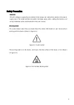
Страница 7: ...bling information and wiring installation will be described within this user manual Warning Labels The caution label means that you should check the certain information on user manual when working with the device Shown in Figure 1 1 Figure 1 1 Caution Label This warning label is on the device and means that the surface of the device is hot Shown in Figure 1 2 Figure 1 2 Hot Surface Warning Label ...

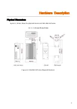
Страница 8: ...4 Hardware Description Physical Dimensions Figure 2 1 below shows the physical dimensions of EG5 0501 SFP series W x D x H is 54mm x 99mm x 142mm Figure 2 1 EG5 0501 SFP Series Physical Dimensions ...

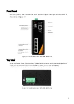
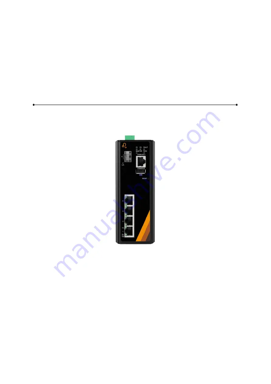
Страница 9: ... shown below in Figure 2 2 Figure 2 2 The Front Panel of EG5 0501 SFP Series Top View Figure 2 3 below shows the top panel of the EG5 0501 SFP series switch that is equipped with one 6 pin removal terminal block connector for dual DC power inputs 12 48VDC Figure 2 3 Top Panel View of EG5 0501 SFP Series ...

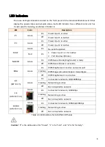
Страница 10: ...ASTER Green On ERPS Owner Mode Ring Master is ready Off ERPS Owner Mode is not active RING Green On ERPS Ring Network is active and works well Flashing ERPS Ring works abnormally or misconfigure Off ERPS Ring Network is not active L A SFP Port 5 Green On Connected to network 100 1000Mbps Flashing Networking is active Off Not connected to network 1G LAN Port 1 4 Green On Connected to network 1000Mb...

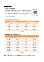
Страница 11: ...traight Through Cable Pin Number Signal Pin Number Signal Pin Number Signal Pin Number Signal 1 RX 3 TX 1 RX 1 TX 2 RX 6 TX 2 RX 2 TX 3 TX 1 RX 3 TX 3 RX 6 TX 2 RX 6 TX 6 RX Table 2 5 1000BASE T RJ 45 Pin Assignments Table 2 6 Crossover Cable Straight Through Cable Pin Number Signal Pin Number Signal Pin Number Signal Pin Number Signal 1 TP0 3 TP1 1 TP0 1 TP1 2 TP0 6 TP1 2 TP0 2 TP1 3 TP1 1 TP0 3 ...

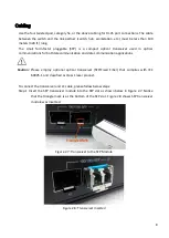
Страница 12: ...ommunication and data communication applications Caution Please employ optional optical transceiver SFP Fixed Fiber that complies with IEC 60825 1 and classified as Class 1 laser product To connect the transceiver and LC cable please follow below steps Step 1 Insert the SFP transceiver module into the SFP slot as shown below in Figure 2 7 Notice that the triangle mark is at the bottom of the SFP s...

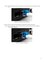
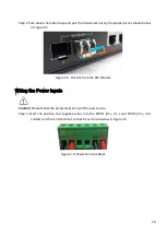
Страница 13: ...Figure 2 9 Figure 2 9 LC Connector to the Transceiver To remove the LC connector from the transceiver please follow the steps shown below Step 1 Press the upper side of the LC connector from the transceiver and pull it out to release as shown below in Figure 2 4 Figure 2 4 Remove LC Connector ...

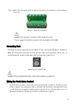
Страница 14: ... 5 Figure 2 5 Pull Out from the SFP Module Wiring the Power Inputs Caution Please follow the below steps to insert the power wire Step 1 Insert the positive and negative wires into the PWR1 V1 V1 and PWR2 V2 V2 contacts on the terminal block connector as shown below in Figure 2 6 Figure 2 6 Power Terminal Block ...

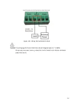
Страница 15: ...he ground screw to the grounding surface prior to connecting devices The grounding screw symbol is shown blow in Figure 2 14 Figure 2 14 Grounding screw Caution Using a shielded cable achieves better electromagnetic compatibility Wiring the Fault Alarm Contact The fault alarm contact is in the middle of the terminal block connector as the picture shows below in Figure 2 By inserting the wires it w...

Страница 16: ...15 Wiring the Fault Alarm Contact Caution The wire gauge for the terminal block should range between 12 24 AWG If only using one power source jumper Pin 1 to Pin 5 and Pin 2 to Pin 6 to eliminate power fault alarm ...

Страница 17: ... and DIN Rail Bracket Follow the steps below to learn how to hang the industrial Ethernet switch Step 1 Use the screws to install the DIN Rail bracket on the rear side of the industrial Ethernet switch Caution The torque for tightening the screws on the device is 3 5 in lbs Step 2 To remove the DIN Rail bracket do the opposite from Step 1 Step 3 After the DIN Rail bracket is installed on the rear ...

Страница 18: ...pull down the bracket on to the rail as shown below in Figure 3 3 Figure 3 3 Stable the Switch on DIN Rail Step 5 Check if the bracket is mounted tightly on the rail Step 6 To remove the industrial Ethernet switch from the rail do the opposite from the above steps ...

Страница 19: ...e industrial Ethernet switch Step 3 Use the screws to screw the wall mounting bracket on the industrial Ethernet switch Caution The torque for tightening the screws on the device is 3 5 in lbs Step 4 Use the hook holes at the corners of the wall mounting bracket to hang the industrial Ethernet switch on the wall Step 5 To remove the wall mount bracket do the opposite from the steps above Figure 3 ...

Страница 20: ...ation Step 3 To hang the industrial Ethernet switch on a DIN Rail or wall please refer to the Mounting Installation section Step 4 Power on the industrial Ethernet switch and then the power LED light will turn on If you need help on how to wire power please refer to the Wiring the Power Inputs section Please refer to the LED Indicators section for LED light indication Step 5 Prepare the twisted pa...

Страница 21: ...ll as other cables Be careful when handling them so as to not trip over Do not under any circumstance insert foreign objects of any kind into the heat dissipation holes located in the different faces of the device This may not only harm the internal layout but might cause harm to user as well Do not under any circumstance open the device for any reason Please contact your dealer for any repair nee...

Страница 22: ...assist in identifying problems the switch can be easily monitored with the LED indicators which help to identity if any problems exist Please refer to the LED Indicators section for LED light indication If the power indicator LED does not turn on when the power cord is plugged in the user may have a problem with the power cord Check for loose power connections power losses or surges at the power o...

Отзывы: