


7
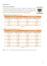
Cabling
Use the four twisted-pair, category 5e, or the above cabling for RJ-45 port connections. The cable
between the switch and the link partner (switch, hub, workstation, etc.) must be less than 100 meters
(328 ft.) long.
Wiring the Power Inputs
Caution:
Please follow the below steps to insert the power wire.
Attention:
Veuillez suivre les étapes ci-dessous pour insérer le câble d'alimentation.
Step 1
Insert the positive and negative wires into the PWR1 (V1+, V1-) and PWR2 (V2+, V2-) contacts
on the terminal block connector as shown below in Figure 2.4.
Figure 2.4: Power Terminal Block
Step 2
Tighten the wire-clamp screws to prevent the wires from loosening, as shown below in Figure
2.5.
Figure 2.5: Power Terminal Block
Caution:
Only use copper conductors, 105°C, tighten to 7 in-lbs (0.79 Nm). The wire
gauge for the terminal block should range between 18~20 AWG.
Attention:
Utilisez uniquement des conducteurs en cuivre, 105 ° C, serrer à 7 in-lbs
(0,79 Nm). Le calibre des fils du bornier doit être compris entre 18 et 20 AWG.
Содержание CEG2-0800 Series
Страница 1: ...CEG2 0800 CEG2 0800 T...


