


Mechanical installation
Mounting of g500 short/servo adapters with clamping connection
Mounting the shrink disc
27
Lenze ¯ MA 12.0018 ¯ 2.0
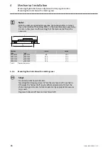
4.4.6.1
Mounting the shrink disc
Depending on the design, the shrink discs may be equipped with a rotating cover
(protective cap, pos. 1).
Note!
This cover is fitted to the shrink disc on delivery.
1.
5.
1
1
2
2
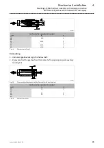
Fig. 11
Shrink disc cover
1
Protection cover
2
Clamping screws
1. Remove protective cap (1), if available.
2. Check machine shaft:
–
Diameter in fit tolerance h6
–
Material yield point Re > = 360 MPa
–
E−module approx. 206 kN/mm
2
–
Surface roughness R
z
£
15
m
m
3. Thoroughly clean and
degrease
hollow shaft bore and machine shaft.
Note!
Thoroughly degrease the bore over the
entire
hollow shaft length to
make sure that remainders of the anticorrosion agent will not be carried
off into the area of the shrink disc when pushing on the machine shaft.
4. Slightly loosen clamping screws (2) one after the other, do
not
unscrew!
5. Push drive onto machine shaft.
6. Slightly tighten clamping screws manually.
7. Tighten clamping screws (2) one after the other (see Fig. 12) in several passes,
with rising torque, evenly until the indicated screw−tightening torque (see Tab. 7 )
is reached at all screws.
Содержание g500 Series
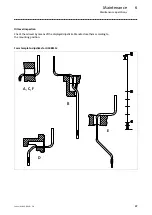
Страница 38: ...Maintenance Maintenance operations 6 38 Lenze MA 12 0018 2 0 Form template dipsticks for G50BS122 A B C D E F...
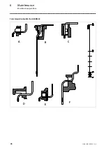
Страница 39: ...Maintenance Maintenance operations 6 39 Lenze MA 12 0018 2 0 Form template dipsticks for G50BS140 A B C D E F...
Страница 40: ...Maintenance Maintenance operations 6 40 Lenze MA 12 0018 2 0 Form template dipsticks for G50BS166 C B D F A E...
Страница 43: ...Notes 43 Lenze MA 12 0018 2 0...


