Mechanical installation
Mounting of g500 short/servo adapters with clamping connection
Torque plate assembly
47
Lenze ¯ MA 12.0018 ¯ 4.1
4.3.14
Torque plate assembly
¯
In order to prevent tensioning, the machine shaft should run with good
concentricity.
¯
Use screws and nuts of the 8.8 property class.
¯
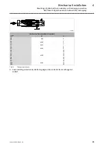
Manufacture washers according to the dimensions indicated in the table below if
they are not included in the scope of supply.
¯
Surface roughness of washers and the fixing strap approx. Rz 25.
¯
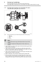
Mount the rubber buffers with the washers in the fashion shown (Fig. 16 ) on
both sides of the gearbox torque plate and at the fixing strap of your machine.
¯
Tighten the screws until the rubber buffers are pre−stressed by the dimension
D
c7.
¯
Tighten the screwed connection using 2 nuts to secure it.
Screws, nuts, and the fixing strap at the machine are not included in the scope of supply
c
7
c
c
6
c
6
d
5
d
D
g50BS113...g50BS245
D
c
c
6
d
5
d
g50BS280...g50BS319
Fig. 16
Dimensions of washers and rubber buffers
Gearbox
Dimensions
Pretension
Washer
Code
Type
d [mm]
D [mm]
c [mm]
D
c
7
[mm]
d
5
[mm]
c
6 min.
[mm]
G50BS113
g500−S130
11
30
12
1
30
2.5
G50BS122
g500−S220
11
30
12
1
30
2.5
G50BS140
g500−S400
13
40
12
1
37
3
G50BS166
g500−S660
13
40
12
1
37
3
G50BS195
g500−S950
13
40
12
1
37
3
G50BS221
g500−S2100
17
50
2x12
2
50
3
G50BS231
g500−S3100
21
60
2x12
2
60
4
G50BS245
g500−S4500
26
72
2x12
2
72
5
G50BS280
g500−S8000
25
80
40
7
100
10
G50BS314
g500−S14000
31
120
50
5
140
12
G50BS319
g500−S19000
31
120
50
7
140
12
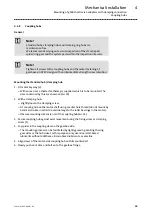
Note!
Solvents, oils, greases, and fuels damage the rubber elements. Be
absolutely sure to prevent contact with these substances!

