Configuration
General information about the system bus (CAN)
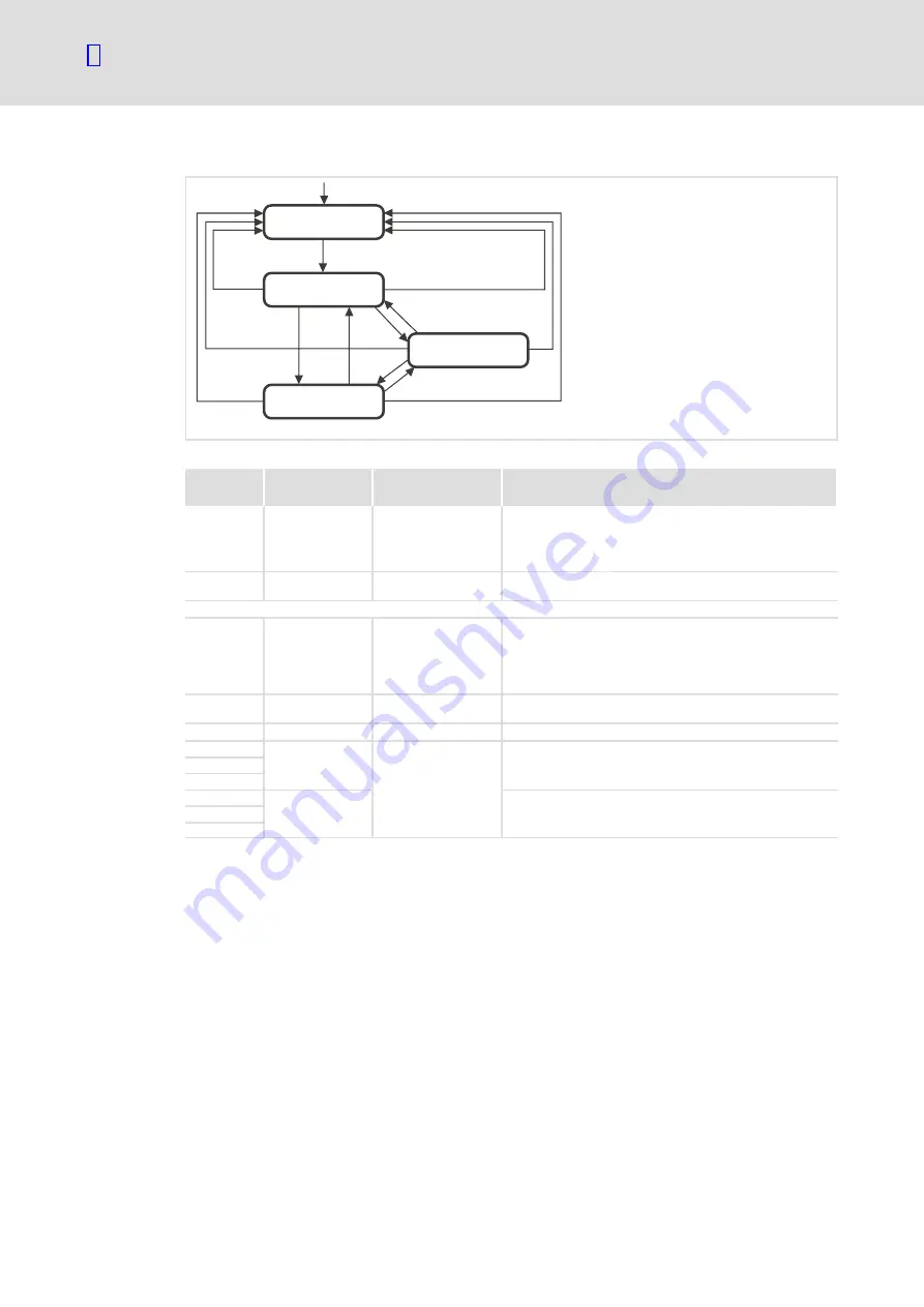
Communication phases of the CAN network (NMT)
80
EDBCSXE040 EN 6.0
State transitions
(3)
(11)
(10)
(9)
(8)
(6)
(7)
(5)
(4)
(2)
(1)
(13)
(12)
(14)
Initialisation
Pre-Operational
Stopped
Operational
E82ZAFU004
Fig. 8−3
State transitions in the CAN network (NMT)
State
transition
Command
(hex)
Network status after
change
Effect on process or parameter data after state change
(1)
−
Initialisation
When the mains is switched on, the initialisation is started automatically.
During the initialisation the controller is not involved in the data
exchange.
After the initialisation is completed, the node changes automatically to
the "Pre−Operational" status.
(2)
−
Pre−operational
In this phase the master decides how the controllers take part in the
communication.
From here, the states are changed over by the master for the entire network. A target address included in the command specifies the receiver/s.
(3), (6)
01 xx
Operational
Network management telegrams, sync, emergency, process data (PDO)
and parameter data (SDO) are active (corresponds to "Start Remote
Node")
Optional:
In case of change, event−controlled and time−controlled process data
(PDO) are sent once.
(4), (7)
80 xx
Pre−operational
Network management telegrams, sync, emergency, and parameter data
(SDO) are active (corresponds to "Enter Pre−Operational State")
(5), (8)
02 xx
Stopped
Only network management telegrams can be received.
(9)
81 xx
Initialisation
Initialisation of all parameters in the communication module with the
values stored (corresponds to "Reset Node")
(10)
(11)
(12)
82 xx
Initialisation of communication−relevant parameters (CiA DS 301) in the
communication module with the values stored (corresponds to "Reset
Communication")
(13)
(14)
xx = 00
hex
With this assignment, all devices connected are addressed by the telegram. The
state can be changed for all devices at the same time.
xx = node ID
If a node address is specified, only the state of the addressed device will be
changed.
Содержание ECSDE012
Страница 1: ...EDBCSXE040 y Ä y ä Operating Instructions ECS ECSEExxx ECSDExxx ECSCExxx Power supply module ...
Страница 3: ... 3 EDBCSXE040 EN 6 0 ECSEE_002A ...
Страница 168: ...Index 12 168 EDBCSXE040 EN 6 0 W Warning 68 112 Warranty 12 X XT EMZ9371BC keypad Diagnostics 123 Parameter setting 72 ...


