


Electrical installation
Installation according to EMC (installation of a CE−typical drive system)
22
GHB 13.0001−EN EN 3.0
Principle circuit diagram
Note!
The described terminal assignment complies with the delivery status. You can
alter the terminal assignment via the operating software.
(
Software Manual 931 E)
1
2
3
4
5
6
7
8
9
10
11
12
13
14
15
16
PE
5
-BR
4
+BR
1
U
7
2
V
3
W
PE
K10
K11
L1
N
PE
1/PE AC 230 V
F1
F2
R
931E
X5
X3
X2
GND
DOUT 0
DIN 4
DIN 5
DIN 6
DIN 7
DIN 8
S1
S2
S3
S4
S5
S6
DIN 9
+AIN 0
+AMON 0
+AMON 1
+AIN 1
-AIN 0
-AIN 1
DOUT 1
DOUT 2
X4.1
X4.2
1
UL
2
UL
3
BR
4
24V
5
24V
6
GND
7
GND
M
3~
KTY
X7
X8
X10
~
~
=
=
24 V DC
24 ... 48 V DC
GND
ZZZ
470
470
560
560
RB
PES
PES
PES
PES
PES
PES
PE
931E_009
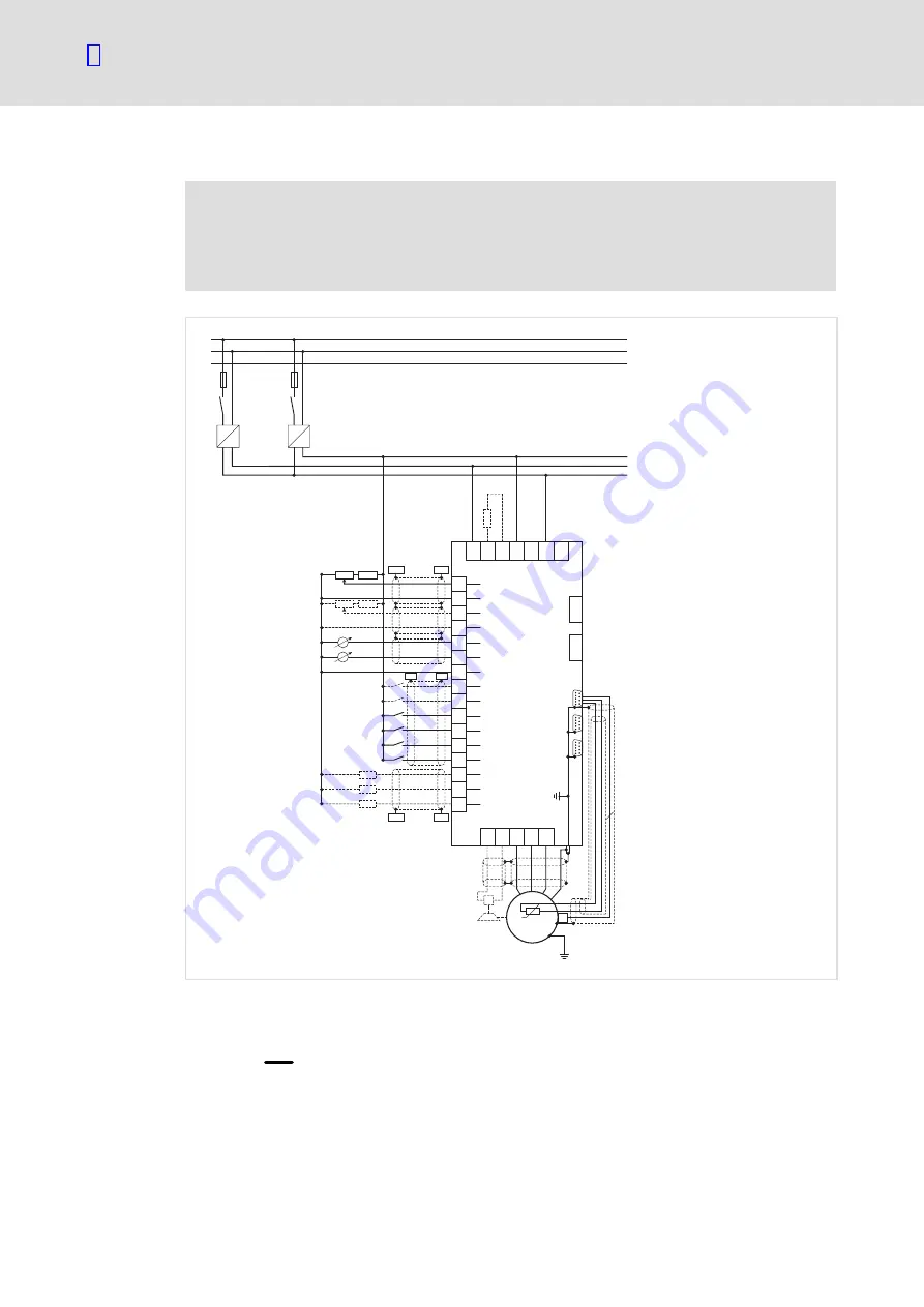
Fig. 3
Basic circuit diagram: installation according to EMC
F1, F2 primary−side fusing of the power supply units, consider the rules of conductor protection
RB
external brake resistor
PES
large−surface connection of the shield to PE
minimum wiring required for operation
S1 =
reversal of rotation direction
S2 =
jog value selection
S3 =
quick stop
S4 =
limit switch 1
S5 =
limit switch 2
S6 =
controller enable
efesotomasyon.com - Lenze