


Firmware
≤
02
.00
- D
M
S
2.
1
EN -
0
3/
201
1
L
16
7
8400 motec | Software Manual
Drive a
ppl
ic
ati
on
Terminal assignment of the control modes
7.5
Terminal assignment of the control modes
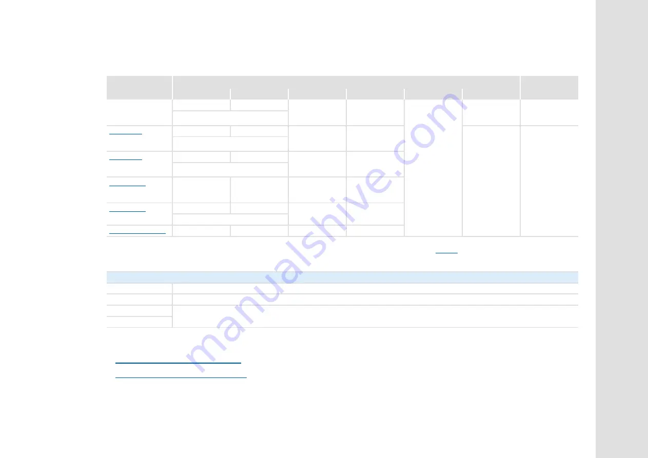
The following table shows which functions are assigned to the digital terminals in the different control modes.
Related topics:
User-defined terminal assignment
Control mode "Network (MCI/CAN)"
Assignment of the digital terminals
Relay output
Control mode
DI1
DI2
DI3
DI4
DI5
DO1
NO / COM
Local mode
(see mounting instructions)
Setpoint of P2
Fixed setpoint 2
Manual DC-
injection braking
Change of
direction of
rotation
1
Release holding
brake manually
2
Status
"Drive is ready to
start"
3
Status
"An error has
occurred"
3
Fixed setpoint 3
Fixed setpoint 1
Fixed setpoint 2
Manual DC-
injection braking
Change of
direction of
rotation
Status
"Drive is ready to
start"
Status
"An error has
occurred"
Fixed setpoint 3
Fixed setpoint 1
Fixed setpoint 2
Quick stop
Change of
direction of
rotation
Fixed setpoint 3
Change of
direction of
rotation
Manual DC-
injection braking
MPotUp
MPotDown
Fixed setpoint 1
Fixed setpoint 2
Cw/QSP
Ccw/QSP
Fixed setpoint 3
Quick stop
-
-
-
1
If the direction of rotation is permanently set to "left" via DIP1/switch 2, DI4 has no influence in local mode.
2
In the Lenze setting, the brake control is switched off (not active).
Set operating mode in
3
Applies to the setting DIP1/switch 8 = "OFF". If DIP1/switch 8 = "ON", both status signals have been interchanged.
Abbreviations used:
MPotUp Motor potentiometer: Increase speed
MPotDown Motor potentiometer: Decrease speed
Cw/QSP Fail-safe selection of the direction of rotation in connection with quick stop
(Cw = clockwise rotation; Ccw = counter-clockwise rotation)
Ccw/QSP
Содержание 8400 motec Series
Страница 375: ...L 375 ...